


ST750
G
ENERAL
H
ANDBOOK
667/HB/33750/000
Page 74
Issue 6
PL7
Pin No
Signal Phase Drive O/P
Softwire kit
Cableform
667/1/27877/000
10
Not used (for isolation purposes)
11
Red Phase D
Red
RB
12
Not used (for isolation purposes)
13
Amber Phase D
Yellow
YB
14
Amber Phase D
15
Not used (for isolation purposes)
16
Green Phase D
Green
GB
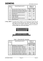
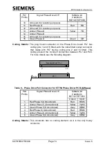
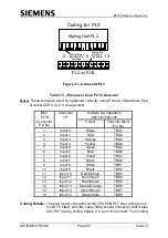
Coding Details:
The plug mount connector on the Phase Drive board PL7 has
coding pins 1 and 16 fitted, with the cable fitted socket connector
that mates with PL7 having coding pins 2 and 15 fitted. This
coding prevent the incorrect connection between PL7 and PL6.
For more details see the following diagram:
PL7
Mating Half PL7
16
1
2
15
PCB
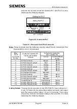
Table 8
– Phase Drive PL8 Connector for ST750 Phase Driver PCB (6 Phase)
PL8
Pin No
Signal Phase Drive O/P
Softwire kit
Cableform
667/1/27877/050
Colour
Ident
1
Red Phase 5 (Unmonitored)
Red
RED5
2
Amber Phase 5 (Unmonitored)
Yellow
YLW5
3
Green Phase 5 (Unmonitored)
Grey
GRN5
4
Red Phase 6 (Unmonitored)
Red
RED6
5
Amber Phase 6 (Unmonitored)
Yellow
YLW6
6
Green Phase 6 (Unmonitored)
Grey
GRN6
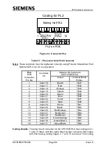
Coding Details:
This connector has no coding element, as it is the only 6-way
connector.