ST750
G
ENERAL
H
ANDBOOK
667/HB/33750/000
Page 50
Issue 6
4.5 FUSES
Figure 42 on page 115 lists the types and placing of fuses in the ST750. Fuses
should only be replaced by ones of a similar rating and type.
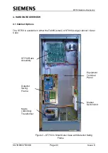
4.6 Mains Dimming Transformer
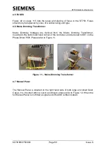
Mains Dimming Voltages are derived from the Mains Dimming Transformer,
mounted in the bottom left hand corner of the controller, and delivered to SK1 on the
Phase Driver PCB. Please refer to Figure 11.
Figure 11
– Mains Dimming Transformer
4.7 Manual Panel
The Manual Panel is situated on the right hand side of both large and small Outer
Cases. It is mounted within a secure enclosure, please refer to Figure 12. When the
full Manual Panel is not fitted a signals on/off switch is fitted instead.


