ST750
G
ENERAL
H
ANDBOOK
667/HB/33750/000
Page 81
Issue 6
PL5
Pin No
External Lamp Monitoring Sensors
8
External Sensor 36
– White
9
External Sensor 37
– Red
10
External Sensor 37
– White
11
External Sensor 38
– Red
12
External Sensor 38
– White
13
External Sensor 39
– Red
14
External Sensor 39
– White
15
External Sensor 40
– Red
16
External Sensor 40
– White
Note that the ST750LED Phase Driver PCB with LV CLS (NLM) monitoring only has
connections on PL5 for External Sensors 38 and 40 (Phase B and Phase D Waits).
Coding & Wiring Details:
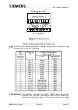
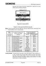
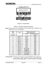
Connector PL5 is a 20-way Berg connector that has a
side flange coding element, which mates with the
associated slot of the IDC board mounted 16-way
connector. The pin positions 1, 2, 19 & 20 on the Berg
connector are not used for wiring purposes but are used
to provide a stop for the IDC board mounted connector
locking levers. See the following diagram:
PCB Mounted
IDC Connector
Free Standing
Berg Connector
Pin 1
Four Shaded
Pin Positions
are not used
Coding
Slot
Coding
Flange
Connector PL5 and its Mating Half (Berg
Connector) Viewed from the Top
Figure 30 - Connector PL5
Instead of driving all the signals at the 230V nominal supply, the ST750 is capable
of driving the Wait indicators or all the pedestrian phase signals directly with an ELV
48V lamp supply.
Switching the supply from 230V to 48V requires fuses and links on the lamp switch
card to be re-arranged as detailed in Section 5.13. The required arrangement also


