ST750
G
ENERAL
H
ANDBOOK
667/HB/33750/000
Page 25
Issue 6
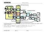
Figure 1
–Theoretical Crossing
2.4.3 Calculation of Average Signal Lamp Power
Calculate the total average signal lamp power as follows, using the bright figures in
Table 3.
Total average signal lamp power is the sum of the signal lamp power plus the sum
of the Wait indicator power.
Assuming that HI lamps take 63W each, the theoretical crossing (Figure 1)
calculation would be:
One lamp per signal head @ 63W x 12 signal heads
=
756W
Wait indicators at 40W x 4
=
160W
Total average signal lamp power
=
916W
2.4.4
Intersection’s Power Requirements for Running Costs Estimate
The following worked example is based upon a 230V/240V mains supply.
1. Calculate the total average controller power
2. Calculate the total average lamp power for the junction as shown in 2.4.3
3. Add the total average signal lamp power to the total average controller power
Total average controller power is calculated as follows:
Average Controller power + Average Detector Power. See section 2.4.1.
A controller is rated at 40 watts (single or dual Pedestrian Controller).
For the purposes of this calculation Siemens ST4R/ST4Sdetector cards are rated at
3W per card.
This gives the total average junction power, which may be used to estimate running
costs.
i.e. Total average junction power
=
Total average signal lamp power +
Total average controller power.
Therefore for our theoretical crossing (Figure 1) the total average controller power
is:
1 x Controller
40 W
2 x Siemens ST detectors
6 W
Total average controller power
46 W

