ST750
G
ENERAL
H
ANDBOOK
667/HB/33750/000
Page 86
Issue 6
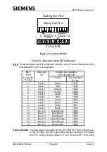
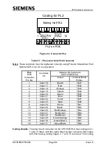
PL2 on PCB
Mating Half PL2
1
6
12
Coding for PL2
Coding Ridge
Removes in 3
positions
Coding Pin
Inserted in
3 Positions
Figure 33 - Connector PL2
Table 17
– Processor Card PL6 Connector
Note:
These terminals must be tightened correctly using Phoenix Screwdriver Part
Number SZS 0.4 x 2,5 or equivalent.
PL6
PCB
Connector
Pin No
Controller
I/P
Softwire Kit Cableform
667/1/27863/100
Colour
Terminal Block
Pin No
1
Input 16
Brown
TBJ1
2
Input 17
Red
TBJ2
3
Input 18
Orange
TBJ3
4
Input 19
Yellow
TBJ4
5
Input 20
Green
TBJ5
6
Input 21
Blue
TBJ6
7
Input 22
Violet
TBJ7
8
Input 23
Slate
TBJ8
9
Input 24
White
TBL1
10
Input 25
Black
TBL2
11
Input 26
Red/Orange
TBL3
12
Input 27
Red/Green
TBL4
13
Input 28
Red/Brown
TBL5
14
Input 29
Green/Orange
TBL6
15
Input 30
Green/Brown
TBL7
16
Input 31
Green/Slate
TBL8
Coding Details:
The plug mount connector on the CPU PCB PL6 has coding pins 1,
7 and 15 fitted, with the cable fitted socket connector that mates
with PL6 having coding ridges 1, 7 and 15 removed. This coding


