ST750
G
ENERAL
H
ANDBOOK
667/HB/33750/000
Page 93
Issue 6
•
For
48V
operation fit only Blue Links in positions LK21 (small pitch), LK16 and
LK19.
Note that the ST750LED Phase Driver PCB with LV CLS (NLM) monitoring always
provides Waits at 48V, so LK16, LK19 and LK21 do not exist.
Note:
Links LK16 and LK19 are accessed through the two rectangular cut outs in
the heatsink cover. See Figure 39 for details. A pair of long nose pliers is required to
insert and extract the handbag links. Both the Red and Blue links are wire shorting
links in the form of a handbag, with a handle to aid insertion and extraction. They fit
into PCB mounted sockets and use spring clips in the socket to make the connection
and fit. These spring clips also retain the link to the PCB; the contacts are gold
plated for low resistance and reliability.
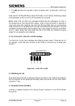
5.13.2.3 Links LK1, LK2, LK3 and LK4 Settings
The links LK1 to LK4 have handbag links fitted as shown below. These should not
be changed. Note that later versions of this PCB do not have any of these links
present.
Connector PL5
L
K
1
L
K
2
L
K
4
L
K
3
Figure 40
– Links LK1 to LK4
5.14 Refitting the LID
Reconnect the earth lead by fitting the Faston connector to the Faston Tag. Replace
the Lid carefully on the equipment mounting frame and secure the Lid to the frame
using the ‘T’ key.
5.15 ON-SITE ST750 TESTING
Connect a suitable handset to the 25-way D-type connector on the ST750 Phase
Drive PCB.

