


Oscillographic Fault Recording
The 7UT6x differential protection is equipped with a fault recording function.
Functional Description
The instantaneous values of measured values
Ι
L1 S1
,
Ι
L2 S1
,
Ι
L3 S1
,
Ι
L1 S2
,
Ι
L2 S2
,
Ι
L3S2
, 3
Ι
0S1
, 3
Ι
0S2
,
Ι
7
,
Ι
8
as well as
Ι
diff L1
,
Ι
diff L2
,
Ι
diff L3
,
Ι
rest L1
,
Ι
rest L2
,
Ι
rest L3
are sampled at intervals of 1,667 ms (for 50 Hz) and stored in a circulation buffer (16 samples per cycle).
When used as single-phase busbar protection, the first six feeder currents
Ι
1
to
Ι
6
are stored instead of the
phase currents, the zero sequence currents are not applicable.
During a system fault, these data are stored over a time span that can be set (5 s at most for each fault
record). Up to 8 faults can be stored. The total capacity of the fault record memory is approx. 20 s. The fault
recording buffer is updated when a new fault occurs, so that acknowledgement is not required. Storage of the
fault recording by the protection fault detection can also be initiated via binary input, the integrated keypad
and display, or via the serial operator or service interface.
The data can be retrieved via the serial interfaces by means of a personal computer and evaluated with the
operating software DIGSI and the graphic analysis software SIGRA 4. The latter graphically represents the data
recorded during the system fault and calculates additional information such as power or rms values from the
measured values. A selection may be made as to whether the measured quantities are represented as primary
or secondary values. Binary signal traces (marks) of particular events e.g. “fault detection”, “tripping” are also
represented.
If the device has a serial system interface, the fault recording data can be passed on to a central device via this
interface. The evaluation of the data is done by the respective programs in the central device. The measured
quantities are referred to their maximum values, scaled to their rated values and prepared for graphic repre-
sentation. Binary signal traces (marks) of particular events e.g. “fault detection”, “tripping” are also repre-
sented.
Where transfer to a central device is possible, the request for data transfer can be executed automatically. It
can be selected to take place after each protection pickup or after a trip only.
Setting Notes
Other settings pertaining to fault recording (waveform capture) are found in the submenu Oscillographic Fault
Records of the Settings menu. Waveform capture makes a distinction between the trigger instant for an oscil-
lographic record and the criterion to save the record (address 901
WAVEFORMTRIGGER
). Normally the trigger
is the pickup of a protective element, i.e. the time 0 is defined as the instant picked up by the first protection
function. The criterion for saving may be both the device pickup (
Save w. Pickup
) or the device trip (
Save
w. TRIP
). A trip command issued by the device can also be used as trigger instant (
Start w. TRIP
); in this
case it is also the saving criterion.
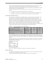
The actual storage time begins at the pre-fault time
PRE. TRIG. TIME
(address 904) ahead of the reference
instant, and ends at the post-fault time
POST REC. TIME
(address 905) after the storage criterion has reset.
The maximum recording duration to each fault (
MAX. LENGTH
) is entered in address 903. Recording to each
fault may take max. 5 seconds. A total of 8 records can be saved. However the total length of time of all fault
records in the buffer may not exceed 20 seconds.
An oscillographic record can be triggered and saved by a change in status of a binary input or via the operating
interface connected to a PC. Storage is then triggered dynamically. The length of a record for these special
triggers is set in address 906
BinIn CAPT.TIME
(upper bound is
MAX. LENGTH
, address 903). Pre-trigger
and post-dropout times are included. If the binary input time is set to
, then the length of the record equals
the time that the binary input is activated (static), or the
MAX. LENGTH
setting in address 903, whichever is
shorter.
2.22.8
2.22.8.1
2.22.8.2
Functions
2.22 Auxiliary Functions
298
SIPROTEC 4, 7UT6x, Manual
C53000-G1176-C230-5, Edition 09.2016
Содержание SIPROTEC 4 7UT6 Series
Страница 394: ...394 SIPROTEC 4 7UT6x Manual C53000 G1176 C230 5 Edition 09 2016 ...
Страница 482: ...482 SIPROTEC 4 7UT6x Manual C53000 G1176 C230 5 Edition 09 2016 ...
Страница 504: ...504 SIPROTEC 4 7UT6x Manual C53000 G1176 C230 5 Edition 09 2016 ...
Страница 522: ...522 SIPROTEC 4 7UT6x Manual C53000 G1176 C230 5 Edition 09 2016 ...
Страница 528: ...528 SIPROTEC 4 7UT6x Manual C53000 G1176 C230 5 Edition 09 2016 ...
Страница 538: ...538 SIPROTEC 4 7UT6x Manual C53000 G1176 C230 5 Edition 09 2016 ...
Страница 664: ...664 SIPROTEC 4 7UT6x Manual C53000 G1176 C230 5 Edition 09 2016 ...
Страница 666: ...666 SIPROTEC 4 7UT6x Manual C53000 G1176 C230 5 Edition 09 2016 ...
Страница 683: ...Z Zero sequence currents 109 Index SIPROTEC 4 7UT6x Manual 683 C53000 G1176 C230 5 Edition 09 2016 ...
Страница 684: ...684 SIPROTEC 4 7UT6x Manual C53000 G1176 C230 5 Edition 09 2016 ...


