


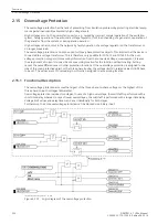


Overvoltage Protection
The overvoltage protection has the task of preventing from insulation problems by protecting electrical equip-
ment against inadmissible abnormally high voltage levels.
High voltages occur in the power station sector, e.g. caused by incorrect manual operation of the excitation
system, faulty operation of the automatic voltage regulator, (full) load shedding of a generator, separation of
the generator from the system or during island operation.
High voltages can also occur in the network by faulty operation of a voltage regulator on the transformer or
on longer weak load.
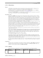
The overvoltage protection can only be used for three-phase protective objects. This implies that the device is
connected to a voltage transformer. This is therefore only possible for 7UT613 and 7UT633. As the over-
voltage protection only gets its measuring information from the connected voltage measurement, it leaves
the assignment of currents to one side or a measuring location for the function without coating. Setting
causes the same differences as in other protection functions. If the overvoltage protection is assigned to one
side of the main protective object or the three-phase busbar, the voltage limits in related values (U/UN) have
to be set. The values are set to secondary in volts when assigned to a measuring location.
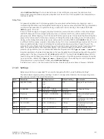
Functional Description
The overvoltage protection assesses the largest of the three phase-to-phase voltages or the highest of the
three phase-to-earth voltages (adjustable).
Overvoltage protection includes two stages. In case of a high overvoltage, the switchoff is performed with a
short-time delay, whereas in case of lower overvoltages, the switchoff is performed with a longer time delay.
Voltage limit values and delay times can be set individually for both stages.
Furthermore, the entire overvoltage protection can be blocked vie a binary input.
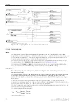
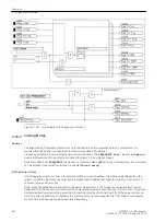
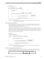
[logikdia-ueberspannungsschutz, 1, en_GB]
Figure 2-107
Logic diagram of the overvoltage protection
2.15
2.15.1
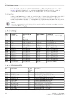
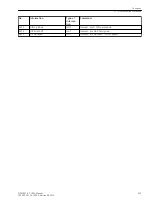
Functions
2.15 Overvoltage Protection
236
SIPROTEC 4, 7UT6x, Manual
C53000-G1176-C230-5, Edition 09.2016
Содержание SIPROTEC 4 7UT6 Series
Страница 394: ...394 SIPROTEC 4 7UT6x Manual C53000 G1176 C230 5 Edition 09 2016 ...
Страница 482: ...482 SIPROTEC 4 7UT6x Manual C53000 G1176 C230 5 Edition 09 2016 ...
Страница 504: ...504 SIPROTEC 4 7UT6x Manual C53000 G1176 C230 5 Edition 09 2016 ...
Страница 522: ...522 SIPROTEC 4 7UT6x Manual C53000 G1176 C230 5 Edition 09 2016 ...
Страница 528: ...528 SIPROTEC 4 7UT6x Manual C53000 G1176 C230 5 Edition 09 2016 ...
Страница 538: ...538 SIPROTEC 4 7UT6x Manual C53000 G1176 C230 5 Edition 09 2016 ...
Страница 664: ...664 SIPROTEC 4 7UT6x Manual C53000 G1176 C230 5 Edition 09 2016 ...
Страница 666: ...666 SIPROTEC 4 7UT6x Manual C53000 G1176 C230 5 Edition 09 2016 ...
Страница 683: ...Z Zero sequence currents 109 Index SIPROTEC 4 7UT6x Manual 683 C53000 G1176 C230 5 Edition 09 2016 ...
Страница 684: ...684 SIPROTEC 4 7UT6x Manual C53000 G1176 C230 5 Edition 09 2016 ...


