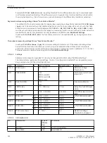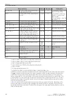
Measured Values
Primary
Secondary
% referred to
Ι
X1;
Ι
X2;
Ι
X3
Currents at the 1-phase further meas-
uring locations X1 to X3
A; kA
A
- - if allocated to side → see
measured value “
Ι
LxSy”
- if allocated to measuring
location → see measured
value “
Ι
LxMz”
- if not allocated → then “
Ι
N-
PRI WDL
Ι
X1..4”
Ι
X4
5)
Current at the further measuring loca-
tion X4
5)
A; kA
A
Ι
1 to
Ι
9
3)
Currents at the measuring inputs
3)
A; kA
A
Rated operational current
Ι
10 to
Ι
12
3)
5)
Currents at the measuring inputs
3)
5)
A; kA
A
Rated operational current
UL1E; UL2E; UL3E
1)
4)
Phase-to-earth voltages at the 3- phase
voltage measuring location
1)
4)
V; kV; MV
V
Operational rated voltage/√3
UL12; UL23; UL31
1)
4)
Phase-to-phase voltages at the 3- phase
voltage measuring location
1)
4)
V; kV; MV
V
Betriebsnennspannung
U1; U2; U0
2)
4)
Positive, negative and zero sequence
component of the voltages at the 3-
phase voltage measuring location
2)
4)
V; kV; MV
V
Operational rated voltage/√3
Uen
4)
Displacement voltage if connected to
the 1-phase voltage measuring input
4)
—
V
Operational rated voltage
U4
4)
Voltage at the 1-phase voltage meas-
uring input
4)
V; kV; MV
V
Operational rated voltage
S, P, Q
1)
4)
Apparent, active and reactive power
1)
4)
MVA,
MW,
kVA; kW
—
Operational rated apparent
power
f
Frequency
Hz
Hz
Rated frequency
cos φ
1)
4)
Power factor
1)
4)
(abs)
—
(abs)
Umess
6)
Voltage from the current measured at
the 1-phase measuring input
6)
V; kV; MV
—
—
S
7)
Apparent power
7)
kVA;
MVA
—
—
U/f
4)
Overexcitation
4)
U
N
/f
N
—
U
N
/f
N
1)
only for 3-phase objects, also for single-phase transformers
2)
only for 3-phase objects, not for single-phase transformers
3)
only for single-phase busbar protection
4)
only for 7UT613 and 7UT633 with voltage measuring inputs
5)
only for 7UT635
6)
if configured and prepared in CFC
7)
calculated from phase currents and rated voltage or measured voltage U
mess
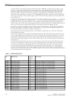
In addition to the measured and calculated values at the measuring locations, measured values are output at
the sides of the main protected object. This makes if possible to obtain the data relevant for the protected
object, even if they are fed to the protected object from several measuring locations, as for example the
higher voltage side (S1) of the transformer. Also, relative values are always referred to a specific side of the
protected object. A current which does not flow into the object from 2 measuring locations (e. g. a current
flowing from one busbar through M1 and M2 to the other busbar) is theoretically zero because no current
flows into the protected object.
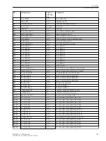
summarizes the operational measured values that are assigned to the sides. Depending on the
device’s order number, connection type, topology and protection functions configured, only a part of the
magnitudes listed there is available. The table does not apply to the single-phase busbar protection, since no
sides are defined there.
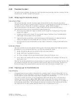
Functions
2.22 Auxiliary Functions
280
SIPROTEC 4, 7UT6x, Manual
C53000-G1176-C230-5, Edition 09.2016
Содержание SIPROTEC 4 7UT6 Series
Страница 394: ...394 SIPROTEC 4 7UT6x Manual C53000 G1176 C230 5 Edition 09 2016 ...
Страница 482: ...482 SIPROTEC 4 7UT6x Manual C53000 G1176 C230 5 Edition 09 2016 ...
Страница 504: ...504 SIPROTEC 4 7UT6x Manual C53000 G1176 C230 5 Edition 09 2016 ...
Страница 522: ...522 SIPROTEC 4 7UT6x Manual C53000 G1176 C230 5 Edition 09 2016 ...
Страница 528: ...528 SIPROTEC 4 7UT6x Manual C53000 G1176 C230 5 Edition 09 2016 ...
Страница 538: ...538 SIPROTEC 4 7UT6x Manual C53000 G1176 C230 5 Edition 09 2016 ...
Страница 664: ...664 SIPROTEC 4 7UT6x Manual C53000 G1176 C230 5 Edition 09 2016 ...
Страница 666: ...666 SIPROTEC 4 7UT6x Manual C53000 G1176 C230 5 Edition 09 2016 ...
Страница 683: ...Z Zero sequence currents 109 Index SIPROTEC 4 7UT6x Manual 683 C53000 G1176 C230 5 Edition 09 2016 ...
Страница 684: ...684 SIPROTEC 4 7UT6x Manual C53000 G1176 C230 5 Edition 09 2016 ...

