3 Functional description of the structure switches
3.4 Controller types (S1, S42 to S45)
Manual
76
SIPART DR21
C73000-B7476-C143-08
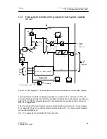
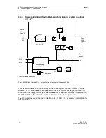
difference monitoring is possible at all times. At S81 = 7, x1 and w can be displayed on the
digital x/w-display in the levels III and IV. A physical display is possible with Pd, Ad, Ed.
At S81 = 2 or 3, the digital x/w-display can be switched to the external nominal ratio wv
E
(display level IV). The digital x/w-display indicates the actual ratio xy in display levels I and III.
Switching between wvi and wv
E
takes place in the same way as in the slave controller
S1 = 1.
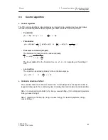
The actual ratio is gained by back calculating the ratio formula with the current process vari-
ables x1, x2:
v
is
=
x1-c5
x2
with
v
ist
= xv (vE -- vA) + vA
the result is for
xv = v
is
-vA
vE-vA
or
xv =
vE-vA
x1-c5
x2
- vA
xv is displayed and is required for x-tracking-mode. For the xv-display, x1 and x2 are limited to
+0.5 % so that the display does not become too restless for small x1 and x2 or flip from positive
to negative in the case of negative x2. The linearization of the commanding process variable x2
or the following process variable x1 is possible (S21).
The linearization then acts on the analog displays and the ratio formation and therefore in-
directly on the digital displays for nominal- and actual ratio. The ratio controller has no nominal
ratio limiting because the ratio factor range already marks the limit.
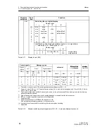
With the Shift key (6) the digital x/w-display can be switched between the display levels I to IV
depending on the position of S81.
In display level II the active nominal ratio wy can be displayed, in dispaly level I/III the actual
ratio xy. The external setpoint wy
E
is displayed in display level IV. The displayed active or exter-
nal nominal ratio can also be adjusted.
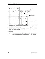
The active setpoint- and actual value is displayed on the analog displays (see table 3-10).
Structure
switches
Posi-
tion
Function
S81
Switching the w/x-digital display
Display order
I
II
III
IV
[0]
x/xv
w/wv
--
--
1
x/xv
w/wv
x1/xv
--
2
x/xv
w/wi1/wv
--
wE/wvE/wi2
3
x/xv
w/wi1/wv
x1/xv
wE/wvE/wi2
4
x/xv
--
--
--
5
--
w/wv
--
--
6
--
--
x1/xv
--
7
xv
wv
x1
w
Identification of the displayed variables by the w- or x-signal lamp:
1 = steady light, 0.5 = flashing light, 0 = off
Display order
I
II
III
IV
1
0
0.5 (0 at S81=6)
0
x-signal lamp
0
1
0
0,5
w-signal lamp
Table 3-10
Display levels (S81)
Содержание SIPART DR21
Страница 1: ...SIPART DR21 C73000 B7476 C143 08 1 SIPART DR21 6DR 210 Edition 08 2010 Manual ...
Страница 2: ...SIPART DR21 C73000 B7476 C143 08 2 ...
Страница 16: ...1 General Part Fundamental control technology terms Manual 16 SIPART DR21 C73000 B7476 C143 08 ...
Страница 148: ...4 Installation 4 2 Electrical Connection Manual 148 SIPART DR21 C73000 B7476 C143 08 ...
Страница 180: ...5 Operation 5 5 CPU self diagnostics Manual 180 SIPART DR21 C73000 B7476 C143 08 ...
Страница 192: ...6 Commissioning 6 7 Manual setting of the control parameters Manual 192 SIPART DR21 C73000 B7476 C143 08 ...
Страница 234: ...9 General explanation of abbreviations for SIPART DR Manual 234 SIPART DR21 C73000 B7476 C143 08 ...
Страница 242: ...Manual 242 SIPART DR21 C73000 B7476 C143 07 ...


