3 Functional description of the structure switches
3.4 Controller types (S1, S42 to S45)
Manual
58
SIPART DR21
C73000-B7476-C143-08
D
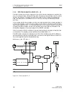
Actual value- and setpoint display
A red and a gree analog display with 1.7 % resolution are arranged on the front module. The
green display is assigned to the setpoint, the red display to the actual value. A red, 4-digit
digital display is used for displaying both the setpoint- and the actual value. Since only one
display is available, the displayed variable is switched using the key (6). The scope of the
display is controlled by the structure switch S81. The type of displayed variable is identified
by the signal lamps (4) and (5).
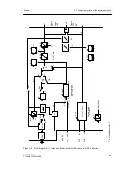
The two analog displays always indicate the active setpoint and the current actual value.
The difference between the two displays is the control difference xd or the control error
xw = --xd. The digital actual value-setpoint display also displays the current actual value/set-
point except in the ratio controllers (ratio controller actual ratio/setpoint ratio). The digital
display shows the setpoint before the setpoint ramp (ratio controller: nominal ratio after the
setpoint ramp).
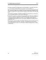
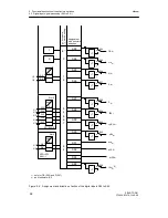
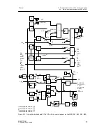
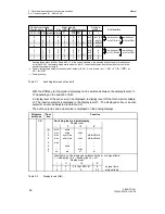
The following symbols are used in the block diagrams below to simplify the representation:
Display type
digital display
↗
analog display
0000
I... IV
x
0000
Display range adjustable with dP, dA, dE
Display levels of the digital display
displayed variables x, w, xv or wv
D
Display range
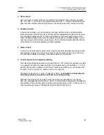
The
digital display
for x or w is a four-digit 7-segment display. The display range for the
x-and w-display is set together with the parameter dP (decimal point), dA (start value) and
dE (end value) in the structuring mode oFPA.
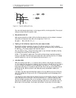
With dA the numeric value is set which is to be displayed at arithmetic value 0 (correspond-
ing to 0 % display in the analog displays). With dE the numeric value is set which is to be
displayed at arithmetic value 1 (corresponding to 100 % display in the analog displays). With
dP the decimal point is set as a fixed point. If the start value is set less than the end value,
an increasing display is given with increasing arithmetic values and vice versa. The number
range for the start- and end value respectively is from -1999 to 9999, outside these ranges,
--oFL and oFL is displayed in the case of overmodulation in the process operation level. The
factory setting is 0.0 to 100.0 %.
With the refresh rate parameter dr (onPA) the digital displays can be settled down in the
case of restless process variables. Non-linear process variables can be represented physi-
cally correctly by the linearization.
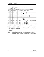
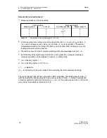
The display range set with dP, dA and dE is transferred depending on the controller type
(S1) to the parameters and setpoints which can be assigned to the displayed variable:
With the appropriate assignment, this also applies for the limit value alarms A1 to A4, see
chapter 3.10.3, page 117.
Содержание SIPART DR21
Страница 1: ...SIPART DR21 C73000 B7476 C143 08 1 SIPART DR21 6DR 210 Edition 08 2010 Manual ...
Страница 2: ...SIPART DR21 C73000 B7476 C143 08 2 ...
Страница 16: ...1 General Part Fundamental control technology terms Manual 16 SIPART DR21 C73000 B7476 C143 08 ...
Страница 148: ...4 Installation 4 2 Electrical Connection Manual 148 SIPART DR21 C73000 B7476 C143 08 ...
Страница 180: ...5 Operation 5 5 CPU self diagnostics Manual 180 SIPART DR21 C73000 B7476 C143 08 ...
Страница 192: ...6 Commissioning 6 7 Manual setting of the control parameters Manual 192 SIPART DR21 C73000 B7476 C143 08 ...
Страница 234: ...9 General explanation of abbreviations for SIPART DR Manual 234 SIPART DR21 C73000 B7476 C143 08 ...
Страница 242: ...Manual 242 SIPART DR21 C73000 B7476 C143 07 ...

