3
Functional description of the structure switches
3.4 Controller types (S1, S42 to S45)
Manual
SIPART DR21
C73000-B7476-C143-08
69
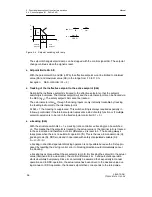
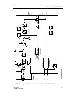
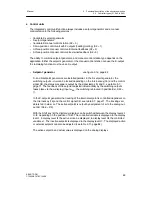
The DDC-mode is signaled like the tracking mode in the other controller types by the lit y-Exter-
nal-LED. The status of the control signal CB and the Internal/External key is displayed by the
LEDs
C
and Internal. During the DDC-mode the setpoint is prepared by tracking to the com-
puter failure. The setpoint is always displayed which would become active after the computer
failure.
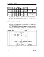
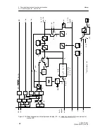
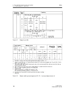
With S50 a choice is made between x-tracking and wi, with S44 the safety setpoint is preset.
With S49 the priority between DDC-mode and manual mode is determined. If DDC-mode has
priority over manual mode, you can select with the manual-automatic switching whether
operation is to continue after a computer failure in automatic- or manual mode. If you need to
intervene manually in computer operation, you have to switch to Internal-mode in addition to
switching over to manual mode, then the LEDs Internal (17) and Manual (12) light up, the LED
y-External (13) goes out, the non-lit LED C (18) still indicates computer standby.
If manual mode has priority over DDC-mode you can switch directly from computer operation to
manual operation. Then the Manual LED (12) lights, the y-External LED (13) goes out, the dark
LEDs Internal (17) and C (18) still indicate computer standby of the controller or computer
standby.
Automatic mode is always switched to here in the event of a computer failure.
D
DDC-control unit
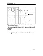
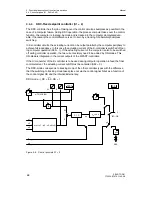
The DDC-control unit function is obtained with S49 = 0 and with S51 = 2 (manual mode
only). In computer operation the manipulated variable is fed through y
N
, manual operation is
always active after a computer failure. If you want to switch over to manual operation during
computer operation, the computer operation must be switched off with the Internal key (16).
The actual value can be indicated on the actual value display.
SH as a flag pointer or wi can be indicated on the setpoint display.
Содержание SIPART DR21
Страница 1: ...SIPART DR21 C73000 B7476 C143 08 1 SIPART DR21 6DR 210 Edition 08 2010 Manual ...
Страница 2: ...SIPART DR21 C73000 B7476 C143 08 2 ...
Страница 16: ...1 General Part Fundamental control technology terms Manual 16 SIPART DR21 C73000 B7476 C143 08 ...
Страница 148: ...4 Installation 4 2 Electrical Connection Manual 148 SIPART DR21 C73000 B7476 C143 08 ...
Страница 180: ...5 Operation 5 5 CPU self diagnostics Manual 180 SIPART DR21 C73000 B7476 C143 08 ...
Страница 192: ...6 Commissioning 6 7 Manual setting of the control parameters Manual 192 SIPART DR21 C73000 B7476 C143 08 ...
Страница 234: ...9 General explanation of abbreviations for SIPART DR Manual 234 SIPART DR21 C73000 B7476 C143 08 ...
Страница 242: ...Manual 242 SIPART DR21 C73000 B7476 C143 07 ...


