4 Installation
4.2 Electrical Connection
Manual
SIPART DR21
C73000-B7476-C143-08
133
4.2.3
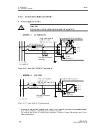
Connection of the options modules
4.2.3.1 Modules for analog measuring inputs
D
6DR2800-8J
(U or I-input)
+
GND
GND
U
H
I
4L
+U
H
U
+
0/2 ... 10 V
0/0.2 ... 1 V
x5=x6/10 V
x4=x5/1 V
(x8=x9)
(x7=x8)
I
0/4 ... 20 mA
x4=x5/1 V
(x7=x8)
U
factory setting 1 V, x4=x5 (and x7=x8)
Set AI3 in slot 1 with S6
measuring range 0 to 1 V, 10 V, 20 mA or
AI4 in slot 2 with S7
0.2 V, 2 V, 4 mA to 1 V, 10 V, 20 mA
311
4
392
3
312
2
1
12
311
4
392
3
312
2
1
12
--
+
GND
I
1)
possible load resistances of other controllers
2)
x7, x8, x9 omitted from the circuit board
C73451--A3000-L106
311
4
392
3
312
2
1
12
--
L+
9
1)
0 to
500
Ω
1 V/10 V
49,9
Ω
GND
+
--
x4
x5 x6
x7
x8 x9 2)
1 V 10 V
6DR2800-8J
I
2L
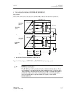
Figure 4-17 Connection U/I-module 6DR2800-8J
Содержание SIPART DR21
Страница 1: ...SIPART DR21 C73000 B7476 C143 08 1 SIPART DR21 6DR 210 Edition 08 2010 Manual ...
Страница 2: ...SIPART DR21 C73000 B7476 C143 08 2 ...
Страница 16: ...1 General Part Fundamental control technology terms Manual 16 SIPART DR21 C73000 B7476 C143 08 ...
Страница 148: ...4 Installation 4 2 Electrical Connection Manual 148 SIPART DR21 C73000 B7476 C143 08 ...
Страница 180: ...5 Operation 5 5 CPU self diagnostics Manual 180 SIPART DR21 C73000 B7476 C143 08 ...
Страница 192: ...6 Commissioning 6 7 Manual setting of the control parameters Manual 192 SIPART DR21 C73000 B7476 C143 08 ...
Страница 234: ...9 General explanation of abbreviations for SIPART DR Manual 234 SIPART DR21 C73000 B7476 C143 08 ...
Страница 242: ...Manual 242 SIPART DR21 C73000 B7476 C143 07 ...


