3
Functional description of the structure switches
3.6
Controller output structures (S2, S49 to S55)
Manual
SIPART DR21
C73000-B7476-C143-08
109
D
Control system coupling via the serial interface
As of software version A5 in addition to the DDC controller (S1 = 2) the SPC controller
(S1 = 1) a parallel process operation is possible in all controller types via the serial interface.
The control signals Int and Hi (via He
ES
at S51 = 3/4, see chapter 3.3, page 50) and the pro-
cess variables wi and y
H
can be written at S85
≥
2 via the serial interface so that switching
from internal to external setpoint and Automatic/Manual switching is possible in all controller
types. If the internal setpoint wi or the manual manipulated variable y
H
is active it can also
be changed by the SES or the adjusting keys on the front panel. Since the SES can only
adjust absolutely and not incrementally, it is advisable to use the setpoint ramp (tS) or the
dynamic manipulated variable with tP and tM to avoid steps.
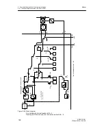
This parallel operation using the serial interface can be locked at S51 = 3 by RC = Int
∨
CB
(see figure 3-3, page 53). This locking facility for the operation via SES on the controller
front is only useful in the controller types fixed setpoint controller with a setpoint (S1 = 5) and
follow-up controller without Internal/External switching (S1 = 6) because in all other controller
types both the Internal key and the control signal CB have other additional functions.
At S51 = 4 this locking facility is omitted and operation is always parallel to the front keys.
To avoid simultaneous actuation by the controller front and the SES the last switching action
can be read on the process control system. For this, a status bit is set when writing Int
ES
and He
ES
which is only reset when the front keys Int or Hi are actuated. By requesting the
status bit, the process control system can issue a warning when the last operation took
place via the front.
If the last operation took place via the SES the warning SES flashes for 3 s in the x/w dis-
play when the Internal key or the Manual key is pressed. This initial pressing of the keys
does not activate a switching function, only when the keys are pressed again is the desired
switching function triggered.
At S84 = 1 writing of status signals Si
ES
... to ...tSH
ES
is locked by /RC.
If the last operation took place via the serial interface the warning SES flashes for 3 s in the
x/w display when the internal key or the manual key is pressed. This initial pressing of the
keys does not activate a switching function, only when the keys are pressed again is the de-
sired switching function triggered.
At S84 = 2 writing of status signals Si
ES
... to ...tSH
ES
is locked by CB.
At S84 = 3*) the status signals Si
ES
... to ...tSH
ES
are always available via the serial interface
(siehe figure 3-3, page 53).
*) as of software version C1
Содержание SIPART DR21
Страница 1: ...SIPART DR21 C73000 B7476 C143 08 1 SIPART DR21 6DR 210 Edition 08 2010 Manual ...
Страница 2: ...SIPART DR21 C73000 B7476 C143 08 2 ...
Страница 16: ...1 General Part Fundamental control technology terms Manual 16 SIPART DR21 C73000 B7476 C143 08 ...
Страница 148: ...4 Installation 4 2 Electrical Connection Manual 148 SIPART DR21 C73000 B7476 C143 08 ...
Страница 180: ...5 Operation 5 5 CPU self diagnostics Manual 180 SIPART DR21 C73000 B7476 C143 08 ...
Страница 192: ...6 Commissioning 6 7 Manual setting of the control parameters Manual 192 SIPART DR21 C73000 B7476 C143 08 ...
Страница 234: ...9 General explanation of abbreviations for SIPART DR Manual 234 SIPART DR21 C73000 B7476 C143 08 ...
Страница 242: ...Manual 242 SIPART DR21 C73000 B7476 C143 07 ...


