5 Operation
5.4 Configuration modes
Manual
166
SIPART DR21
C73000-B7476-C143-08
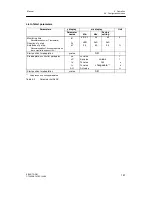
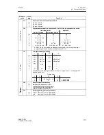
StrS -- structure switch list
Structure
switch
switch
posi-
tion
Function
S1
Controller type
[0]
Fixed value/three-component controller/controller with 2 internal setpoints
1
Slave / synchronization / SPC controller
2
DDC controller
3
Ratio controller
4
Control unit / process display
5
Fixed value controller with 1 setpoint for control system coupling (as of software version-A7)
ngs
6
Slave controller without internal/external switching for control system coupling (as of software
version -A7)
se
tti
n
S2
Output structure
sic
s
[0]
K--output
B
as
i
1
S--output
two-position controller with 2 outputs heating/cooling *)
B
2
S--output:
three-position step controller for motorized drives, internal feedback *)
3
S--output:
three-position step controller for motorized drives, external feedback *)
S3
Mains frequency suppression
[0]
50 Hz
1
60 Hz
S4
Input signal AI1 and transmitter fault message
[0]
0...20 mA
without MUF
1
0...20 mA
with MUF
2
4...20 mA
without MUF
3
4...20 mA
with MUF
S5
Input signal AI2 and transmitter fault message
[0]
0...20 mA
without MUF
1
0...20 mA
with
MUF
2
4...20 mA
without MUF
3
4...20 mA
with
MUF
S6
Input signal AI3 (slot 1) and transmitter fault message
[0]
0...20 mA
or U,R,P,T
without MUF
1
0...20 mA
or U,R,P,T
with MUF
2
4...20 mA
or U
without MUF
3
4...20 mA
or U
with MUF
put
s
4
UNI module Min
at sensor break
without MUF
g
inp
u
5
UNI module Max
at sensor break
without MUF
alog
6
UNI module Min
at sensor break
with MUF
A
nal
o
7
UNI module Max
at sensor break
with MUF
A
S7
Input signal AI4 (slot 2) and transmitter fault message
[0]
0...20 mA
or U,R,P,T
without MUF
1
0...20 mA
or U,R,P,T
with MUF
2
4...20 mA
or U
without MUF
3
4...20 mA
or U
with MUF
S8
Input signal AI3 (slot 1) with UNI--module (only active at S6=4/5/6/7)
[0]
mV (linear), with measuring range plug U or I (no active sensor break monitoring)
1
Thermocouple with internal reference point
2
Thermocouple with external reference point
3
PT100 4--wire connection incl. supply lines
4
PT100 3--wire connection incl. supply lines
5
PT100 2--wire connection incl. supply lines
6
Resistance potentiometer with
R < 600
7
Resistance potentiometer with 600
≤
R < 2.8 k
*) see chapter 6.3 “Adaptation of the S-controller to the actuating drive”, page 183
Содержание SIPART DR21
Страница 1: ...SIPART DR21 C73000 B7476 C143 08 1 SIPART DR21 6DR 210 Edition 08 2010 Manual ...
Страница 2: ...SIPART DR21 C73000 B7476 C143 08 2 ...
Страница 16: ...1 General Part Fundamental control technology terms Manual 16 SIPART DR21 C73000 B7476 C143 08 ...
Страница 148: ...4 Installation 4 2 Electrical Connection Manual 148 SIPART DR21 C73000 B7476 C143 08 ...
Страница 180: ...5 Operation 5 5 CPU self diagnostics Manual 180 SIPART DR21 C73000 B7476 C143 08 ...
Страница 192: ...6 Commissioning 6 7 Manual setting of the control parameters Manual 192 SIPART DR21 C73000 B7476 C143 08 ...
Страница 234: ...9 General explanation of abbreviations for SIPART DR Manual 234 SIPART DR21 C73000 B7476 C143 08 ...
Страница 242: ...Manual 242 SIPART DR21 C73000 B7476 C143 07 ...

