3
Functional description of the structure switches
3.1 General
Manual
SIPART DR21
C73000-B7476-C143-08
47
3
Functional description of the structure switches
3.1
General
The controller is adapted to the respective job by structure switches. The factory setting corre-
sponds to the most usual setting of the individual functions so that only few structure switches
usually need to be set selectively during commissioning. However, it is recommendable to com-
pare the compatibility of the individual structure switch settings with the task in any case.
The structure switches S1 and S2 are fundamentally important. With S1 the controller type is
set and thus the processing of command variable, main controlled variable and auxiliary con-
trolled variables up to control difference generation determined. With S2 the controller output
structure is set and thus the processing of the automatic-manual-, safety- and tracking variables
as well as the manipulated variable output determined as a K- or S-output.
The functions of structure switches S3 to S81 correspond to the logical order of signal proces-
sing. S82 and S83 describe the restart conditions, S84 to S91 the transmission procedure of
the serial interface.
The structure switches are described in this order in the following description.
.
NOTE
The control elements on the front are shown on page 5 and specified by the
digits in the text in brackets. The structure switches are designated by S**.
3.2
Analog input signal processing (S3 to S21)
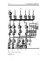
see fig. 3-1, page 49
Each of the maximum 4 analog inputs is fed through an AD-converter which performs the 50 or
60 Hz interference suppression (S3) by averaging over 20 or 16 2/3 ms. Then standardization
to 0 to 100% calculated value takes place per channel of the signal range 0 to 20 mA or 4 to
20 mA. The UNI-module is structured with S6> 3 and S8 determines its input signal. S9 deter-
mines the thermocouple type when a thermocouple input is chosen. The temperature unit for
PT100- or thermocouple signals is determined with S10.
At the same time S4 to S7 decide whether operation is to take place with or without range moni-
toring (transmitter fault). A separate AD-converter routine without averaging is responsible for
monitoring so that the manual mode which is possible with S50 comes into action bumplessly in
the event of a transmitter fault. The monitor signals per channel on dropping below -2.5% or
exc106.25 % with a hysteresis of 0.25 % on the digital x/w-display. By an OR link of all
single messages the group transmitter fault MUF is formed which can be assigned to the digital
outputs and negated optionally (see figure 3-1, page 49 and chapter 3.8, page 111). Only the
analog inputs selected with the transmitter fault monitor are monitored, displayed on the front
panel (the appropriate position stays dark in the case of analog inputs not selected with trans-
mitter fault) and signaled with the OR link. The error message is acknowledged with the Shift
key (12). The fault message signal via the OR link is available until the selected analog inputs
are back in the working range.
Содержание SIPART DR21
Страница 1: ...SIPART DR21 C73000 B7476 C143 08 1 SIPART DR21 6DR 210 Edition 08 2010 Manual ...
Страница 2: ...SIPART DR21 C73000 B7476 C143 08 2 ...
Страница 16: ...1 General Part Fundamental control technology terms Manual 16 SIPART DR21 C73000 B7476 C143 08 ...
Страница 148: ...4 Installation 4 2 Electrical Connection Manual 148 SIPART DR21 C73000 B7476 C143 08 ...
Страница 180: ...5 Operation 5 5 CPU self diagnostics Manual 180 SIPART DR21 C73000 B7476 C143 08 ...
Страница 192: ...6 Commissioning 6 7 Manual setting of the control parameters Manual 192 SIPART DR21 C73000 B7476 C143 08 ...
Страница 234: ...9 General explanation of abbreviations for SIPART DR Manual 234 SIPART DR21 C73000 B7476 C143 08 ...
Страница 242: ...Manual 242 SIPART DR21 C73000 B7476 C143 07 ...


