3 Functional description of the structure switches
3.5 Control algorithm
Manual
92
SIPART DR21
C73000-B7476-C143-08
z S2
0
x1 S1
5
x
2
y
n
y
a
S4
7
c6
Kp
·
c7
1)
i
P
tn
S2
P
(S
27)
Kp
S4
6
S4
6
0
AH
I
tF
0/
1/
3
0
1
0
1
+
+
+
-1
c6
z
y
o
YA
,Y
E
y
o
=y
n
-(
kp
·
c7
·
xd
+
c6
·
z)
Co
ntro
ls
tructure
1 2 3 4
xd
p
1)
c7
in
P
I-
oper
at
ion
=
1
c7
in
P
-oper
at
ion
1
to
9.
999
adjus
table
-1
-1
-1
-1
vv
tv
+
Output structures S2
+
p
d
y
o
=y
n
-p
Input signal processing figure 3-1, page 49 and controller types S1
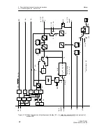
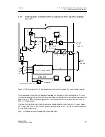
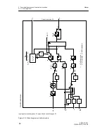
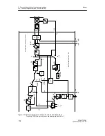
Figure 3-21 Block diagram controller structure
Содержание SIPART DR21
Страница 1: ...SIPART DR21 C73000 B7476 C143 08 1 SIPART DR21 6DR 210 Edition 08 2010 Manual ...
Страница 2: ...SIPART DR21 C73000 B7476 C143 08 2 ...
Страница 16: ...1 General Part Fundamental control technology terms Manual 16 SIPART DR21 C73000 B7476 C143 08 ...
Страница 148: ...4 Installation 4 2 Electrical Connection Manual 148 SIPART DR21 C73000 B7476 C143 08 ...
Страница 180: ...5 Operation 5 5 CPU self diagnostics Manual 180 SIPART DR21 C73000 B7476 C143 08 ...
Страница 192: ...6 Commissioning 6 7 Manual setting of the control parameters Manual 192 SIPART DR21 C73000 B7476 C143 08 ...
Страница 234: ...9 General explanation of abbreviations for SIPART DR Manual 234 SIPART DR21 C73000 B7476 C143 08 ...
Страница 242: ...Manual 242 SIPART DR21 C73000 B7476 C143 07 ...

