3
Functional description of the structure switches
3.8
Digital output signal processing (S57 to S75)
Manual
SIPART DR21
C73000-B7476-C143-08
111
3.8
Digital output signal processing (S57 to S75)
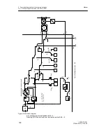
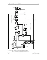
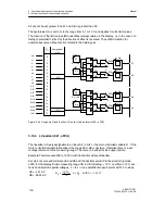
The message signals RB, RC ... MUF, +
Δ
w and -
Δ
w are assigned to the digital outputs DO1 to
DO8 by the structure switches S58 to S68 and can be negated optionally with the structure
switches S69 to S75 (
Δ
w and -
Δ
w) (see figure 3-30, page 112).
The digital outputs DO1, DO2 and DO7, DO8 of the standard controller can be extended with
the options modules 4DO 24 V +2DI (6DR2801-8E) or 2DO-relay 35 V (6DR2801-8A) in slot 3
to a maximum 6 or 8 digital outputs respectively. When using 4DO 24 V +2DI in slot 3 by DO3
to DO6, when using 2DO-relay 35 V in slot 3 by DO3 and DO4.
When using options modules in slot 3, structure switch S22 must be set according to the as-
signment, otherwise there will be error messages (see chapter 5.5, page 179 ).
The control signals
±
Δ
y (positioning increments of the S-controllers) are not negatable but
they can be assigned to one of the binary outputs DO1, DO2, DO7 or DO8. The setting of S57
has priority over assignments with S58 to S68. The assigned digital outputs for
±
Δ
y are not
stored in “ST5” and “BABE” (refresh-time approx. 20 ms). Decription of ST5 and BABE: see
operating instructions “Serial SIPART 6DR190x Bus Interface”.
On assigning different control signals to the same digital output an OR-function of the control
signals is produced (exception at
±
Δ
y).
Unassigned digital outputs (switch position 0) are low and can be set by SES at S85 = 2. All
digital outputs have wired-or-diodes.
D
Functional explanation of the digital message signals.
RB
No computer standby of the controller
This signal indicates that the controller is in internal operation, i.e. not in computer
standby.
RC
Computer operation
This signal indicates the negated computer operation RC = Int
∧
CB and controls the
setpoint switching or DDC-operation.
H
Manual mode
The controller is in manual mode, triggered either by manual/automatic-switching on the
front of the controller (Hi) or by the digital input signal He if the control signals Si,
±
yBL
and N (with tracking over manual operation priority) are Low.
Nw
Tracking operation
The controller is in tracking mode when the control signals Si,
±
yBL and H (in manual
over tracking operation priority) are Low and the conmtrol signal N is High.
A1/A2
Alarm 1 and 2
indicate response of the limit value alarms A1 and A2.
A3/A4
Alarm 3 and 4
indicates response of the limit value alarms A3 and A4.
MUF
Transmitter fault
The instruments’s analog input signals can be monitored for exceeding of the measuring
range. This signal gives a group alarm if an error is detected.
Δ
y
positioning increments for the
Δ
y-adjustment in S-controllers
Δ
w
positioning increments for the
Δ
w-adjustment
, only for control unit/process display
(S1 = 4)
Содержание SIPART DR21
Страница 1: ...SIPART DR21 C73000 B7476 C143 08 1 SIPART DR21 6DR 210 Edition 08 2010 Manual ...
Страница 2: ...SIPART DR21 C73000 B7476 C143 08 2 ...
Страница 16: ...1 General Part Fundamental control technology terms Manual 16 SIPART DR21 C73000 B7476 C143 08 ...
Страница 148: ...4 Installation 4 2 Electrical Connection Manual 148 SIPART DR21 C73000 B7476 C143 08 ...
Страница 180: ...5 Operation 5 5 CPU self diagnostics Manual 180 SIPART DR21 C73000 B7476 C143 08 ...
Страница 192: ...6 Commissioning 6 7 Manual setting of the control parameters Manual 192 SIPART DR21 C73000 B7476 C143 08 ...
Страница 234: ...9 General explanation of abbreviations for SIPART DR Manual 234 SIPART DR21 C73000 B7476 C143 08 ...
Страница 242: ...Manual 242 SIPART DR21 C73000 B7476 C143 07 ...


