3 Functional description of the structure switches
3.3 Digital input signal processing (S23 to S41)
Manual
50
SIPART DR21
C73000-B7476-C143-08
3.3
Digital input signal processing (S23 to S41)
D
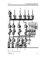
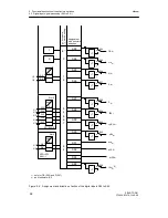
Assignment and direction of effect of the digital inputs (S23 to S40)
see figure 3-2, page 52
The control signals CB, He ...bLS, bLPS, tSH are assigned by the structure switches S23 to
S33, S92 to the digital inputs DI1 to DI7 or the Lo status. The High status is also possible
when assigning CB (S23) and P (S27). The control signals can be negated optionally by the
structure switches S34 to S40.
The digital inputs DI1 and DI2 of the standard controller can be extended by DI3 to DI7 for
example with the option module 5DI (6DR2801-8C) in slot 3 (S22 = 2).
When using the module 4DO 24 V + 2DI (6DR2801-8E) it is possible to extend by two (DI3,
DI4) inputs (S22=1).
When using option modules in slot 3, structure switch S22 must be set according to the as-
signment, otherwise there will be an error message (see chapter 5.5, page 179 ).
All digital inputs can be read by the SES.
D
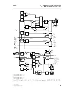
Linking the digital inputs DI1 to DI7 with the control signals via the SES.
(S41, S42, S51 and S85)
see figure 3-3, page 53
The control signal CB (S23) may be available at the digital input (S41) either as a static sig-
nal or as a pulse (key operation on control desk). Every positive edge trips the flip-flop when
selecting the pulse input. In the following descriptions the output status of the flip-flop is as-
sumed as CB.
All control signals (bLb as of software --B3, tSH as of software --B5) can also be specified in
S85 = 2, 3, (4, 5)
1)
via the SES and or-linked with the corresponding control signals by the
digital inputs. Since the top operation hierarchy in a computer link should be with the autar-
chic single controller, the control signals can be switched off by the SES by rounding with
RC = Int
∧
CB via the Internal/External key (16) of the controller or via CB
ES
(optionally
time-monitored) or via CB
DI
(central Computer Fail line) .
In addition the internal flip-flop can be activated at S85 = 2 to 5 parallel to pressing the keys
via Int
ES
.
The CB-signal is formed at S85 = 2, (4)
1)
as an OR-function of CB
ES
via the serial interface
and CB
DI
via a digital input so that operation can take place optionally with one signal.
1)
as of software version --A5
Содержание SIPART DR21
Страница 1: ...SIPART DR21 C73000 B7476 C143 08 1 SIPART DR21 6DR 210 Edition 08 2010 Manual ...
Страница 2: ...SIPART DR21 C73000 B7476 C143 08 2 ...
Страница 16: ...1 General Part Fundamental control technology terms Manual 16 SIPART DR21 C73000 B7476 C143 08 ...
Страница 148: ...4 Installation 4 2 Electrical Connection Manual 148 SIPART DR21 C73000 B7476 C143 08 ...
Страница 180: ...5 Operation 5 5 CPU self diagnostics Manual 180 SIPART DR21 C73000 B7476 C143 08 ...
Страница 192: ...6 Commissioning 6 7 Manual setting of the control parameters Manual 192 SIPART DR21 C73000 B7476 C143 08 ...
Страница 234: ...9 General explanation of abbreviations for SIPART DR Manual 234 SIPART DR21 C73000 B7476 C143 08 ...
Страница 242: ...Manual 242 SIPART DR21 C73000 B7476 C143 07 ...


