Wiring digital inputs/outputs
1. Strip 10 mm of insulation from the wires.
2. Wire the digital inputs of the interface for connection of the sensors.
3. Wire the digital outputs of the interface for connection of the actuators.
4. Insert the cable into the corresponding spring-loaded terminal.
Using shielded cables
When using a shielded cable for the bidirectional inputs/outputs, the following options are
available for the shield connection:
1. Attach the cable shield to a grounded shielding bus immediately after the cable entry point
in the cabinet (strip the insulation off the cable for this purpose).
2. Continue routing the shielded cable as far as the module but do not make a connection to the
shield there.
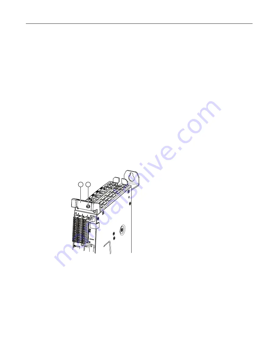
Using a shield connection
1. Remove the fixing bracket of the shield connection.
2. Insert the cable and fasten the fixing bracket.
①
Fixing bracket of the shield connection
②
Torx screw M3/0.8 Nm
Figure 8-10
Shield support
Connecting
8.10 Digital inputs/outputs
NCU 1740
Equipment Manual, 10/2021, A5E51087503B AA
85
Содержание SINUMERIK ONE NCU 1740
Страница 48: ...Dimension drawings 6 1 NCU 1740 dimension drawing NCU 1740 48 Equipment Manual 10 2021 A5E51087503B AA ...
Страница 52: ...Installation 7 4 Mounting the NCU without spacers NCU 1740 52 Equipment Manual 10 2021 A5E51087503B AA ...
Страница 96: ...Technical data 11 3 Recycling and disposal NCU 1740 96 Equipment Manual 10 2021 A5E51087503B AA ...
Страница 156: ...Connectable components 12 3 PP 72 48D PN 2 2A PN NCU 1740 156 Equipment Manual 10 2021 A5E51087503B AA ...
Страница 160: ...Safety symbols NCU 1740 160 Equipment Manual 10 2021 A5E51087503B AA ...


