


5. Evaluate your drive response.
– If the motor decelerates too slowly, then reduce the ramp-down time.
The minimum ramp-down time that makes sense depends on your particular application.
Depending on the Power Module used, for an excessively short ramp-down time, the
converter either reaches the motor current, or the DC link voltage in the converter
becomes too high. Depending on the converter setting, the real braking time exceeds
the set ramp-down time, or the converter goes into a fault condition when braking.
– Extend the ramp-down time if the motor is braked too quickly or the converter goes into
a fault condition when braking.
6. Repeat steps 1 … 5 until the drive behavior meets the requirements of the machine or plant.
You have set the extended ramp-function generator.
Changing the ramp-up and ramp-down times in operation
The ramping up and down time of the ramp-function generator can be changed during
operation. The scaling value can come, e.g. from the fieldbus.
Table 6-45
Parameters for setting the scaling
Parameter
Description
p1138
Up ramp scaling (factory setting: 1)
Signal source for scaling the acceleration ramp.
p1139
Deceleration ramp scaling (factory setting: 1)
Signal source for scaling the deceleration ramp.
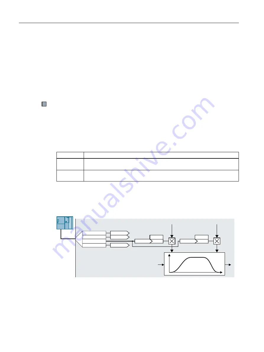
Application example
In the following application example, the higher-level control sets the ramp-up and ramp-down
times of the inverter via PROFIBUS.
5DPSXSWLPH
5DPSXSWLPH
VFDOLQJ
5DPSGRZQWLPH
5DPSGRZQWLPH
VFDOLQJ
5HFHLYHGGDWD
S
\
W
[
\
U>@
U>@
U>@
S
U>@
U>@
3='
3='
3='
3='
Figure 6-40 Application example for changing the ramp-function generator times in operation
Advanced commissioning
6.17 Setpoint calculation
SINAMICS G120C converter
250
Operating Instructions, 09/2017, FW V4.7 SP9, A5E34263257B AF
Содержание SINAMICS G120C
Страница 2: ......
Страница 14: ...Table of contents SINAMICS G120C converter 14 Operating Instructions 09 2017 FW V4 7 SP9 A5E34263257B AF ...
Страница 469: ......


