Copyright © Siemens AG 2010. All rights reserved.
Page
35
ERTEC 400 Manual
Technical data subject to change
Version 1.2.2
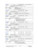
To avoid irritations concerning the interrupt causes it is recommended to reset interrupt bit 4
"INT_QVZ_PCI_STATE" in register "PLL_STAT_REG" at the beginning of 2nd level boot code.
4.2 General Purpose I/O (GPIO)
A maximum of 32 general purpose inputs/outputs are available in the ERTEC 400. After a reset, these are set as
GPIO inputs.
GPIOs [31, 7 : 0] are always available as I/O because no additional functions can be assigned.
GPIOs [30 : 8] have additional function features in the form of interfaces to watchdog, F-counter, UARTs, SPI,
ETM, and MC PLL in the IRT macro.
The direction of the IO can be programmed bit-by-bit in the
"GPIO_IOCTRL“
register.
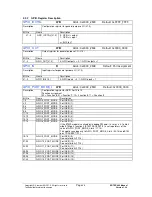
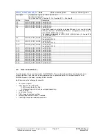
The special I/O function selection can be programmed in the “
GPIO_PORT_MODE_L
”
a
nd
“
GPIO_PORT_MODE_H”
registers and the direction (input or output) in the “
GPIO_IOCTRL
” register.
GPIO inputs [1 : 0] and [31 : 30] can also be used as external interrupt inputs. They are connected at the IRQ
interrupt controller of the ARM946. An interrupt can be generated only with an active High input level, rising edge,
or falling edge (for parameter assignment, refer to Section 2.9.11).
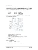
The following figure shows the structure of a GPIO pin as a standard I/O function or as an alternative function.
GPIO(i)
GPIO
IN
GPIO
OUT (i)
Alternate Function 1,2,3 (if Input)
Alternate Function 1,2,3 (if Output)
GPIO
IOCTRL(i)
GPIO_PORT
MODE_L&..._H
(2*i+1, 2*i)
Pin of
ERTEC400
Figure 4: GPIO Cells of ERTEC 400
4.2.1
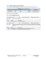
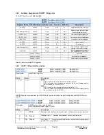
Address Assignment of GPIO Registers
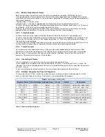
The GPIO registers are 32 bits in width. The registers can be read or written to with 8-bit, 16-bit, or 32-bit
accesses.
GPIO
(Base Address 0x4000_2500)
Register Name
Offset Address
Address Area
Access
Default
Description
GPIO_IOCTRL
0x0000
4 bytes
W/R
0xFFFFFFFF
Configuration register for GPIO
GPIO_OUT
0x0004
4 bytes
W/R
0x00000000
Output register for GPIO
GPIO_IN
0x0008
4 bytes
R
0x00000000
Input register for GPIO
GPIO_PORT_MODE_L
0x000C
4 bytes
W/R
0x00000000
Function assignment of GPIO port
0 to 15
GPIO_PORT_MODE_H
0x0010
4 bytes
W/R
0x00000000
Function assignment of GPIO port
16 to 31
Table 9: Overview of GPIO Registers


