Copyright © Siemens AG 2010. All rights reserved.
Page
16
ERTEC 400 Manual
Technical data subject to change
Version 1.2.2
1.5.7
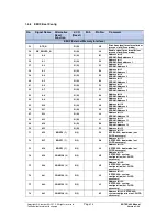
PCI/LBU
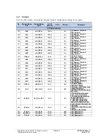
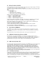
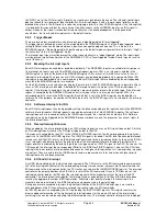
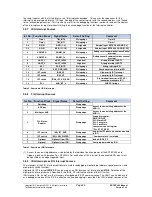
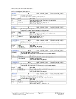
The PCI or LBU interface is selected by setting the “Config 2” configuration pin during the reset phase.
No
.
Signal Name
PCI
Signal Name
LBU
(5)
I/O
(Reset)
Pull-
Pin No.
Comment
PCI/LBU Interface
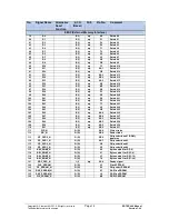
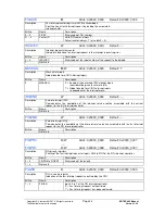
127
AD00
LBU_DB00
B/B (I)
D4
PCI: Address / Data Bit 0
LBU: Data Bit 0
128
AD01
LBU_DB01
B/B (I)
A2
PCI: Address / Data Bit 1
LBU: Data Bit 1
129
AD02
LBU_DB02
B/B (I)
B2
PCI: Address / Data Bit 2
LBU: Data Bit 2
130
AD03
LBU_DB03
B/B (I)
B3
PCI: Address / Data Bit 3
LBU: Data Bit 3
131
AD04
LBU_DB04
B/B (I)
D5
PCI: Address / Data Bit 4
LBU: Data Bit 4
132
AD05
LBU_DB05
B/B (I)
B4
PCI: Address / Data Bit 5
LBU: Data Bit 5
133
AD06
LBU_DB06
B/B (I)
E7
PCI: Address / Data Bit 6
LBU: Data Bit 6
134
AD07
LBU_DB07
B/B (I)
A4
PCI: Address / Data Bit 7
LBU: Data Bit 7
135
CBE0_N
LBU_BE0_N
B/I (I)
D7
PCI: Byte 0 Enable
LBU: Byte 0 Enable
136
AD08
LBU_DB08
B/B (I)
B5
PCI: Address / Data Bit 8
LBU: Data Bit 8
137
AD09
LBU_DB09
B/B (I)
D8
PCI: Address / Data Bit 9
LBU: Data Bit 9
138
AD10
LBU_DB10
B/B (I)
B6
PCI: Address / Data Bit 10
LBU: Data Bit 10
139
AD11
LBU_DB11
B/B (I)
E8
PCI: Address / Data Bit 11
LBU: Data Bit 11
140
AD12
LBU_DB12
B/B (I)
A6
PCI: Address / Data Bit 12
LBU: Data Bit 12
141
AD13
LBU_DB13
B/B (I)
E9
PCI: Address / Data Bit 13
LBU: Data Bit 13
142
AD14
LBU_DB14
B/B (I)
B7
PCI: Address / Data Bit 14
LBU: Data Bit 14
143
AD15
LBU_DB15
B/B (I)
F9
PCI: Address / Data Bit 15
LBU: Data Bit 15
144
CBE1_N
LBU_BE1_N
B/I (I)
B8
PCI: Byte 1 Enable
LBU: Byte 1 Enable
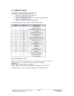
145
PAR
LBU_WR_N
B/I (I)
E10
LBU mode: LBU_CFG=0: Write
control (Low active)
LBU CFG=1: RD/WR Control (0:
WR: 1: RD)
146
SERR_N
LBU_POL_RDY
B/I (I)
B9
PCI mode: Bidirection, open
drain ; ext. PU necessary;
LBU mode: Setting of polarity
for pin; LBU_RDY_N:
0: LBU_RDY_N Low active
1: LBU_RDY_N High active
Input; static (input value must
not be changed after power-up).
147
PERR_N
LBU_RD_N
B/I (I)
A9
LBU mode:
LBU_CFG=0: Read Control (Low
active)
LBU CFG=1: No function
148
STOP_N
LBU_AB00
B/I (I)
D10
LBU: Address Bit 0
149
DEVSEL_N
LBU_AB01
B/I (I)
B10
LBU: Address Bit 1
150
TRDY_N
LBU_AB02
B/I (I)
D11
LBU: Address Bit 2


