


Copyright © Siemens AG 2010. All rights reserved.
Page
73
ERTEC 400 Manual
Technical data subject to change
Version 1.2.2
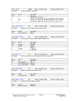
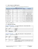
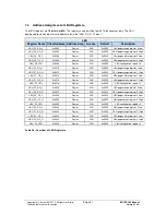
Extended Config
W/R
Addr.: 0x7000_0020 Default: 0x0303_0000
Description
Setting of additional functionalities
Bit No.
Name
Description
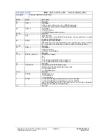
31
----
Reserved
30
TEST_1
Test Mode 1
0: 200 µs delay after system reset (SDRAM power-up)
1: Delay after system reset is immediately terminated
29
TEST_2
Test Mode 2
0: Normal function
1: All SDRAM accesses are misses
28..26
----
Reserved
25
ADB
Active data bus
After each access to the SDRAM, the data bus is driven actively to 1 in order
to support integrated pull-ups.
24
ASDB
Asynchronous active data bus
After each access to the asynchronous area, the data bus is driven actively
to 1 at the end of the Hold phase in order to support integrated pull-ups.
23..20
----
Reserved
19
TEST_3
Test Mode 3
0: Normal function
1: DTR_N = Test Output
18
----
Reserved
17..16
BURST_LENGTH
SDRAM burst length
00: 1
01: 2
10: Full Page, Read INCR_S burst length = 4
11: Full Page, Read INCR_S burst length = 8
15
----
Reserved
14
TRCD/TCD
Time between the SDRAM commands
Activate and read/write, precharge and activate
0: 2 AHB clock cycles
1: 1 AHB clock cycle
13..9
----
Reserved
8
SDSIZE
SDRAM bank size
0: 32-bit data bus
1: 16-bit data bus
7
ATIRQ
0: Timeout watchdog for asynchronous accesses disabled
1: Timeout watchdog for asynchronous accesses enabled
After the watchdog expires (256 AHB clock cycles), an interrupt is triggered.
Setting Bit 7 to 0 deletes interrupt source.
6..0
----
Reserved