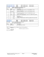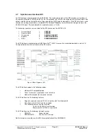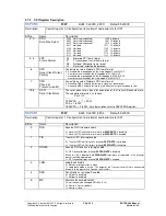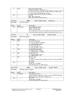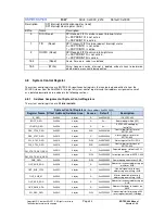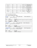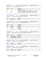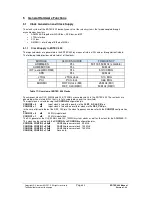
Copyright © Siemens AG 2010. All rights reserved.
Page
64
ERTEC 400 Manual
Technical data subject to change
Version 1.2.2
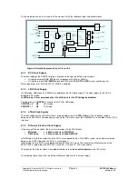
The figure below shows the structure of the clock unit with the individual input and output clocks.
CLKA
12,5 MHz
(PLL-Bypass: 100MHz)
CLKB
Divider
1:2
REF_CLK
25/50MHz
MUX
MUX
CONFIG1
CONFIG0
APLL
12,5 MHz
PLL_IN
(12,5 MHz)
PLL_OUT
(300 MHz)
CONFIG4
CONFIG3
MUX
MUX
MUX
SCANMODE
CLK_ARM
CLK_50
CLK_100
HCLKEN-
Gen.
HCLKEN
(ARM9)
Lock-Timer
Power-up
(650us)
Lock
CLK_IN
Enable
Lock Monitor
PLL_LOCK_STATE
Clock_unit_v2.ppt
BYPASS_CLK_IN
Clock
Generation
0
1
0
1
0
1
OSC
Divider
1:4
MUX
SCAN_CLK(3:0)
(TRACEPKT(3:0))
3
2
0
1
BYPASS_CLK
100MHz
Figure 9: Detailed Representation of Clock Unit
5.1.2
PCI Clock Supply
The clock supply of the AHB PCI bridge is implemented using two different clock inputs.
•
Using the external
CLK_PCI
pin at a frequency of 33 MHz or 66 MHz.
•
Using the internal
CLK_50MHz
clock per SW via the
CLK_CTRL_REG
system control register.
After a power-up reset, AHB clock CLK_50MHz is enabled.
5.1.3
LBU Clock Supply
In LBU mode, AHB clock CLK_50MHz is enabled for the LBU clock supply. The clock supply for the LBU is
disabled in PCI mode.
In LBU mode, it is recommended that the AHB clock for the PCI bridge be disabled.
Configuration pin
CONFIG2
is used to select PCI or LBU mode.
CONFIG2 = 0
LBU mode
CONFIG2 = 1
PCI mode
5.1.4
JTAG Clock Supply
The clock supply for the JTAG interface is implemented using the
JTAG_CLK
pin. The frequency range is
between 0 and 10 MHz. The boundary scan and the ICE macro cell of the ARM946E-S are enabled via the JTAG
interface.
5.1.5
Ethernet Interface Clock Supply
In the case of Ethernet ports, there are two interfaces to the PHY blocks:
•
MII mode
= 2 Ethernet ports to 2 MII-PHYs
•
RMII mode
= 4 Ethernet ports to quad RMII-PHY
In RMII mode, the Ethernet ports and the PHYs are supplied by the CLK_50MHz system clock. Communication
between the ERTEC port and the PHYs is synchronous.
In MII mode, the two PHYs are supplied with one 25 MHz PHY clock. The clock for the Ethernet ports of the
ERTEC 400 is supplied by the MII PHYs via the RX_CLK and TX_CLK clock cables.
The clock for the Ethernet ports is enabled/disabled via the
clock control register
in the IRT switch.
The following figure shows the two different Ethernet modes with the clock supply.


