Chapter 4 - Parameters and Menu Structure
Parameters (M3)
55 | 180
Siemens Industry, Inc.
Siemens BT300 HVAC Drive
DPD01809
Building Technologies
2016-06-07
Structure
Parameter
Default
ID
Description
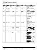
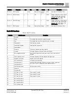
P3.5.1.13
Run Interlock 2
DigIN Slot0.2
1042
Defines the input monitored for proof of the interlock application
when Mot. Interlock Start (P3.2.11) is enabled.
The Drive cannot be started if any of the interlocks are open. This
function can be used for a damper interlock, preventing the Drive
from starting with the damper closed.
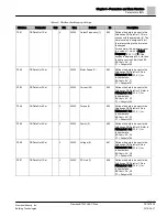
P3.5.1.14
PreHeat ON
DigIN Slot0.1
1044
Used when Preheat Function (P3.1.2.5) is set to 2
0 = No action
1 = Used motor preheat DC current in Stop state
P3.5.1.15
Preset Freq Sel0
DigIN SlotA.4
419
Defines the location for the binary selector 0 used with
PresetFreqMode (P3.3.10), and Preset Freq 1 (P3.3.12), through
Preset Freq 7 (P3.3.18).
P3.5.1.16
Preset Freq Sel1
DigIN SlotA.5
420
Defines the location for the binary selector 0 used with
PresetFreqMode (P3.3.10), and Preset Freq 1 (P3.3.12), through
Preset Freq 7 (P3.3.18).
P3.5.1.17
Preset Freq Sel2
DigIN Slot0.1
421
Defines the location for the binary selector 0 used with
PresetFreqMode (P3.3.10), and Preset Freq 1 (P3.3.12), through
Preset Freq 7 (P3.3.18).
P3.5.1.18
Timer 1
DigIN Slot0.1
447
Defines the location to the rising edge to start timer 1 as
programmed in Timer Functions (P3.11) menu structure.
P3.5.1.19
Timer 2
DigIN Slot0.1
448
Defines the location to the rising edge to start timer 2 as
programmed in Timer Functions (P3.11) menu structure.
P3.5.1.20
Timer 3
DigIN Slot0.1
449
Defines the location to the rising edge to start timer 3 as
programmed in Timer Functions (P3.11) menu structure.
P3.5.1.21
Disable Timer Funct.
DigIN Slot0.1
1499
Enable parameter for all timer functions including Intervals 1-5 and
Timer 1-3 (programmable in Timer Functions (P3.11) menu
structure).
Contact closure = Timer functions and reset timers disabled
Open Contact = Timer functions and reset timers enabled
P3.5.1.22
PID1 Boost SP
DigIN Slot0.1
1047
Defines the location for applying boost to PID1 setpoint.
Contact closure = Boost
Open Contact = No Boost
P3.5.1.23
PID1 Select SP
DigIN Slot0.1
1046
Defines the location to determine which setpoint is to be used with
PID1.
Open Contact = Setpoint 1
Contact Closure = Setpoint 2
P3.5.1.24
PID2 Start Signal
DigIN Slot0.2
1049
Parameter will have no effect if PID2 controller is not enabled in the
basic menu for PID2.
Open Contact = PID2 in stop mode
Contact Closure = PID2 regulating
P3.5.1.25
PID2 Select SP
DigIN Slot0.1
1048
Defines the location to determine which setpoint is to be used with
PID2.
Open Contact = Setpoint 1
Contact Closure = Setpoint 2
P3.5.1.26
Interlock 1
DigIN Slot0.1
426
Defines the location for the interlock feedback for motor 1 when
using the multi-pump feature.
P3.5.1.27
Interlock 2
DigIN Slot0.1
427
Defines the location for the interlock feedback for motor 2 when
using the multi-pump feature.
P3.5.1.28
Interlock 3
DigIN Slot0.1
428
Defines the location for the interlock feedback for motor 3 when
using the multi-pump feature.
P3.5.1.29
Interlock 4
DigIN Slot0.1
429
Defines the location for the interlock feedback for motor 4 when
using the multi-pump feature.
Содержание BT300 LonWorks
Страница 1: ...Siemens BT300 HVAC Drive Operator s Manual DPD01809 Building Technologies 2016 06 07 ...
Страница 8: ......
Страница 179: ......


