


Chapter 4 - Parameters and Menu Structure
Parameters (M3)
54 | 180
Siemens Industry, Inc.
Siemens BT300 HVAC Drive
DPD01809
Building Technologies
2016-06-07
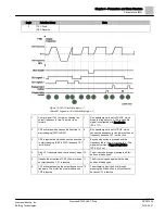
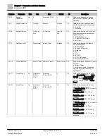
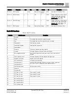
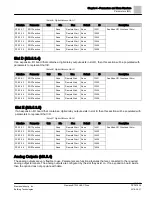
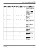
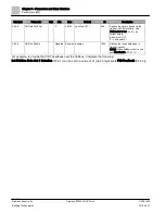
The digital inputs settings are presented in the following table:
Table 31: Digital Inputs Settings.
Structure
Parameter
Default
ID
Description
P3.5.1.1
Ctrl Signal 1 A
(Start Forward)
DigIN SlotA.1
403
Defines the location for selection of Control Signal 1 A as defined by
I/O A Logic (P3.2.6) [Start Forward]
Possible settings are as follows:
TimeChannel.#
DigIN Slot0.#
DigIN SlotA.#
DigIN SlotC.#
DigIN SlotD.#
DigIN SlotE.#
Where # is the channel number or occurrence number.
NOTE:
Slot C, D, and E available if option cards are installed and
contain Digital Input type objects.
P3.5.1.2
Ctrl Signal 2 A
(Start Reverse)
DigIN SlotA.2
404
Defines the location for selection of Control Signal 2 A as defined by
I/O A Logic (P3.2.6) [Start Reverse].
Possible settings are the same as Ctrl Signal 1 A (P3.5.1.1).
P3.5.1.3
Ctrl Signal 1 B
(Start Forward)
DigIN Slot0.1
423
Defines the location for selection of Control Signal 1 B as defined by
I/O B Logic (P3.2.7) [Start Forward].
Possible settings are the same as Ctrl Signal 1 A (P3.5.1.1).
P3.5.1.4
Ctrl Signal 2 B
(Start Reverse)
DigIN Slot0.1
424
Defines the location for selection of Control Signal 2 B as defined by
I/O B Logic (P3.2.7) [Start Reverse].
Possible settings are the same as Ctrl Signal 1 A (P3.5.1.1).
P3.5.1.5
I/O B Ctrl Force
DigIN Slot0.1
425
Defines the location to determine when I/O B Logic (P3.2.7) should
be followed.
Open Contact = I/O A Logic (P3.2.6) is followed.
Contact Closure = I/O B Logic (P3.2.7) is followed.
P3.5.1.6
I/O B Ref Force
DigIN Slot0.1
343
Defines the location to determine when I/O B Ctrl Ref (P3.3.4)
should be followed.
Open Contact = I/O A Ctrl Ref (P3.3.3) is followed.
Contact Closure = I/O B Ctrl Ref (P3.3.4) is followed.
P3.5.1.7
Ext Fault Close
DigIN SlotA.3
405
Defines the location to monitor to generate response to External
Fault (P3.9.2) on contact closure.
Open Contact = OK
Contact Closure = External Fault Active
P3.5.1.8
Ext Fault Open
DigIN Slot0.2
406
Defines the location to monitor to generate response to External
Fault (P3.9.2) on contact open.
Open Contact = External Fault Active
Contact Closure = OK
P3.5.1.9
Fault Reset Close
DigIN SlotA.6
414
Defines the location of fault reset on contact closure (rising edge).
Contact Closure = Reset
P3.5.1.10
Fault Reset Open
DigIN Slot0.1
213
Defines the location of fault reset on open contact (falling edge).
Open Contact = Reset
P3.5.1.11
Run Enable
DigIN Slot0.2
407
Defines the location of the run enable.
Open Contact = Disabled = NOT READY
Contact Closure = Enabled = READY
The VFD is stopped according to the Stop Function (P3.2.5).
NOTE: When fieldbus is used, refer to FB Run Enable (P3.6.9).
P3.5.1.12
Run Interlock 1
DigIN Slot0.2
1041
Defines the input monitored for proof of the interlock application
when Mot. Interlock Start (P3.2.11) is enabled.
The drive cannot be started if any of the interlocks are open. This
function can be used for a damper interlock, preventing the drive
from starting with the damper closed.
Содержание BT300 LonWorks
Страница 1: ...Siemens BT300 HVAC Drive Operator s Manual DPD01809 Building Technologies 2016 06 07 ...
Страница 8: ......
Страница 179: ......