7.5.6.1.1
Common
tab
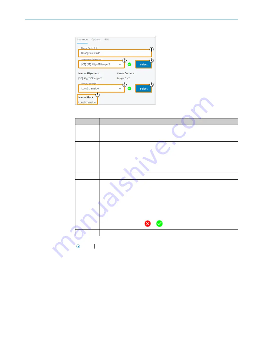
Figure 57: Basic ROI, Common tab
Function
Description
1
Input field for name assignment.
The entered name is preceded by an abbreviation to indicate the camera ([
C1
],
[
C2
]).
2
Select the alignment to which this region will be attached.
Apply the selection by clicking the
Select
button.
Once the region has been assigned to an alignment, the graphical layout can
occur. By default, a region of type Rectangle is shown (in this case a square with
a 300 mm edge length). The upper left point is 100 mm away from the upper left
edge of the image in both dimensions (x and y).
3
Apply the selection.
4
Select a block in the schematic diagram.
Apply the selection by clicking the
Select
button.
As soon as an inspection in a region in this block leads to an NOK result, the
selected block is shown in red on the display.
Several inspections can be assigned to the same block in the schematic diagram
(both inspections use the same block for display). This is the case if, for example,
a check for foreign bodies is to be performed in one region and a check for
screws is to be performed in a neighboring region or a region within the region.
The display changes from
to
once the settings have been applied.
5
Display the currently valid selection.
After clicking the
Teach
button, the ROI is displayed.
NOTE
If the search region is not displayed in the image, the zoom factor may be
too large and the region is outside the display area. Decrease the zoom factor to view
and move the region.
7.5.6.1.2
Options
tab
The
Options
tab is used to configure display or maintenance parameters.
Changes on this page do not affect the status of the taught-in parameters. The status of
the system (indicated by the Teach State) remains unchanged when changes are made
here.
OPERATION
7
8027445/V1-0/2022-06-15 | SICK
O P E R A T I N G I N S T R U C T I O N S | FOS-HVS
59
Subject to change without notice


