Shenzhen Mindray Bio-Medical Electronics Co., Ltd. DC-N2 Скачать руководство пользователя страница 134

9-10 Patient Data Management 

9.4.2 

Patient Data View & Management 

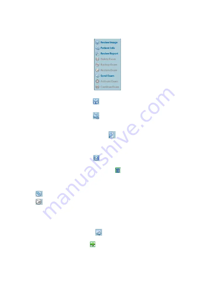
Select the desired patient information in the list. The following menu pops up:   


„

 Review 

Select an exam of a patient, click 

  to enter Review screen. 

„

 Info 

Select an exam of a patient, click 

  on the right side to display the patient information 

of this exam. 

„

 Report 

After you select an exam of a patient, click 

  to view the report of this exam for this 

patient. If no report is generated in the exam, the system prompts that “There is no report 
belongs to the exam”. 

„

 Delete 

Select an exam or a patient, click 

  to delete. However, you cannot delete patient data 

being printed, exported or sent, or delete the current exam. 

To delete an image, select the image and click 

  on the right side.   

„

 Backup/ 

Restore 

You can back up the selected patient data to the system-supported media in order to view 
it on PC, or restore the patient data to the system from an external media. 

: Backup. Click to export the selected patient data to the system-supported media.   

: Restore. Click to import the patient data from an external media. If no external data 

source is connected, then the button is unavailable. 


„

 Send 

To 

The system supports to send data to external memory devices or print. 

z


Select the patient record, click 

  on the menu to send exam data or images of the 

selected record.   

z


Select the image, and click 

  beside the image to send the selected image.   

h


Send patient exam data to USB devices, DVD drive and iStorage. 

h


Send images to USB devices, DVD drive, DICOM storage server, DICOM printer, 
video printer, text/ graph printer and iStorage. 

h


Send images with report to USB devices, DVD drive and iStorage. 

h


Format transfer is available when sending images to USB devices, DVD or 
iStorage. See "9.2.10 Sending Image File" for details. 

Содержание DC-N2

Страница 1: ...DC N2 DC N2T DC N2S Diagnostic Ultrasound System Operator s Manual Basic Volume...

Страница 2: ......

Страница 3: ...ystem Overview 2 1 2 1 Intended Use 2 1 2 2 Contraindication 2 1 2 3 Product and Model Code 2 1 2 4 Product Specifications 2 1 2 4 1 Imaging Mode 2 1 2 4 2 Power supply 2 1 2 4 3 Environmental Conditi...

Страница 4: ...eparation 4 1 4 1 Start an Exam 4 1 4 2 Patient Information 4 1 4 2 1 New Patient Information 4 1 4 2 2 Retrieve Patient Information 4 5 4 3 Select Exam Mode and Probe 4 7 4 3 1 Selecting Exam Mode an...

Страница 5: ...Viewing 5 33 5 10 6 Image Saving and Reviewing in Smart 3D 5 39 6 Display Cine Review 6 1 6 1 Image Display 6 1 6 1 1 Splitting Display 6 1 6 1 2 Image Magnification 6 1 6 1 3 Freeze Unfreeze the Ima...

Страница 6: ...humbnails 9 3 9 2 8 Image Review and Analysis 9 3 9 2 9 iVision 9 5 9 2 10 Sending Image File 9 7 9 3 Report Management 9 7 9 4 Patient Data Management iStation 9 8 9 4 1 Searching a Patient 9 9 9 4 2...

Страница 7: ...1 6 Storage and Transportation 12 10 12 2 Biopsy Guide 12 11 12 2 1 Basic Procedures for Biopsy Guiding 12 13 12 2 2 Needle guided Brackets 12 14 12 2 3 Needle guided Bracket Inspection and Installati...

Страница 8: ...tainty 14 5 14 9 References for Acoustic Power and Safety 14 6 15 Guidance and Manufacturer s Declaration 15 1 16 System Maintenance 16 1 16 1 Daily Maintenance 16 1 16 1 1 Cleaning the System 16 1 16...

Страница 9: ...BeneView WATO BeneHeart are the trademarks registered or otherwise of Mindray in China and other countries All other trademarks that appear in this manual are used only for informational or editorial...

Страница 10: ...personnel This warranty shall not extend to Malfunction or damage caused by improper use or man made failure Malfunction or damage caused by unstable or out of range power input Malfunction or damage...

Страница 11: ...It is the physician s responsibility for diagnostic procedures Mindray shall not be liable for the results of diagnostic procedures 7 Important data must be backed up on external memory media 8 Mindr...

Страница 12: ...recautions exam modes imaging modes preset maintenance and acoustic output etc z Operator s Manual Advanced Volume Describes measurement preset measurements and calculations etc z Operator s Manual Ac...

Страница 13: ...z Buttons The angular bracket indicates buttons knobs and other controls on control panel z Items in menu and buttons in dialog box The square bracket indicates items in menu or buttons in dialog box...

Страница 14: ......

Страница 15: ...harmful ingress of water Main unit IPX0 Probes IPX7 Footswitch 1 pedal type belongs to IPX8 2 pedal and 3 pedal type belong to IP68 According to the degree of safety of application in the presence of...

Страница 16: ...erious injury CAUTION Indicates a potentially hazardous situation that if not avoided may result in minor or moderate injury NOTE Indicates a potentially hazardous situation that if not avoided may re...

Страница 17: ...ctive grounding conductor before turning ON the system Disconnect the grounding cable after turning OFF the system Otherwise electric shock may result 3 For the connection of power and grounding follo...

Страница 18: ...for the recommended peripheral devices Do not connect other devices to the outlet otherwise the rated output power may be exceeded and failure may be resulted Maximum output power of the outlet is 288...

Страница 19: ...that generate radio waves such as cellular telephones transceivers and radio controlled toys in the room where the system is installed z If a person brings a device that generates radio waves near the...

Страница 20: ...the patient for a long time Apply the transducer only for a period of time required for the purpose of diagnosis 9 The system and its accessories are not disinfected or sterilized prior to delivery T...

Страница 21: ...ntal temperature 3 Dusty locations 4 Locations subject to vibration 5 Locations near heat generators 6 Locations with high humidity 5 Turn ON the system only after the power has been turned OFF for a...

Страница 22: ...nly for use with the specified ultrasonic diagnostic system Please refer to the 2 5 2 Transducers Available to select the proper probe 2 The ultrasonic probe must be used only by qualified professiona...

Страница 23: ...erwise Mindray will not be liable for damage caused by other solutions If you have any questions please contact Mindray Customer Service Department or sales representative 9 The probe sheath contains...

Страница 24: ...nging potential negative consequences to the environment and human health For more detailed information with regard to returning and recycling this system please consult the distributor from whom you...

Страница 25: ...abel are described as follows No Warning Labels Meaning 1 Caution Please carefully read this manual before use system 2 Prohibit using system with flammable anesthetics or explosion risk may happen 3...

Страница 26: ......

Страница 27: ...n This system is not intended for ophthalmic use 2 3 Product and Model Code NOTE The functions described in the operator s manual may vary depending upon the specific system you purchased 2 4 Product...

Страница 28: ...d weights z Size 670mm 520mm 1265 1415 mm Depth Width Height Adjustable control panel is configured 670mm 520mm 1315mm Depth Width Height z Net Weight 55kg including one battery 2 5 System Configurati...

Страница 29: ...ginal 9 35C50EB Convex Gynecology Obstetrics Pediatric Abdominal Vascular Urology Body surface 10 65EC10EB Convex intracavitary Gynecology Obstetrics Pediatric Urology Cephalic Transrectal transvagina...

Страница 30: ...le 30 40 50 14G 16G 18G 20G 22G 2 5 3 Options No Item 1 Color Power module 2 PW module 3 IMT module 4 iScape module 5 HPRF 6 DICOM DICOM Basic 7 DICOM Worklist DICOM Basic should be configured first 8...

Страница 31: ...Deskjet Ink advantage Printer K109g HP Officejet Pro 8100 HP Deskjet 1000 J110a EPSON Stylus PHOTO R230 EPSON Stylus PHOTO R270 Footswitch USB type 2 pedal 971 SWNOM 3 pedal 971 SWNOM WARNING This sy...

Страница 32: ...6 Lifting control lever Press to lift the support arm option 7 DVD RW Read and Write DVD drive 8 Probe ports Used to connect the probe The third port for use is an option 9 Placing table Used to place...

Страница 33: ...s 2 Separate video output connecting video printer 3 Composite video signal output connecting video printer 4 Remote control port 5 Audio output left channel 6 Audio output right channel 7 VGA VGA sig...

Страница 34: ...ential terminal Used for equipotential connection that balances the protective earth potentials between the system and other electrical equipment 2 Power outlet Auxiliary power output used to supply p...

Страница 35: ...Battery status indicator Charging light in orange Full light in green Discharge capacity 20 light in green Discharge capacity 20 blinking in orange Discharge capacity 5 blinking in orange rapidly Non...

Страница 36: ...please refer to 11 1 6 Key Config chapter 15 Biopsy Press to show or hide the biopsy guide line 16 Setup Press to open close the preset menu 17 Del Press to delete the comment etc 18 Alphanumeric key...

Страница 37: ...urn to the previous operation or delete the previous item 40 Set Press to confirm an operation same as the left button of a mouse 41 Trackball You can roll the trackball to change the cursor position...

Страница 38: ...utput AC Alternating current Battery Status Indicator Standby indicator Hard disk indicator A Probe port A B Probe port B C Probe port C Product serial number Manufacture date Authorized representativ...

Страница 39: ...ng system failure resulted due to increased system operating temperature 2 Pay extra attention when moving the system on a sloping ground do not move it on a more than 10 sloped plane to avoid system...

Страница 40: ...sure that protective grounding works normally NOTE Make sure to allow sufficient slack in the cable so that the plug will not be pulled out from the socket even if the system is moved slightly If the...

Страница 41: ...plug from the receptacle before disconnecting the equipotential wire otherwise electric shock may result 2 When you connect another device to this system you should use the equipotential wire to conne...

Страница 42: ...ails 2 There shall be no condensation 3 There shall be no distortion damage or dirt on the system and peripheral devices If any dirt is found cleaning shall be performed as defined in section 16 1 1 C...

Страница 43: ...are fully functional 6 The exam date and time are the same as the system date and time and are displayed correctly WARNING 1 If you use a probe giving off excessive heat it may burn the patient 2 If y...

Страница 44: ...ormally z Standby To enter the standby status z Cancel To cancel the operation To shut down the system in a direct way if you cannot do it normally Press and hold the power button for a long time and...

Страница 45: ...ss NOTE On the display the brightness adjustment comes before contrast After readjusting the display s contrast and brightness adjust all presets and peripheral settings 3 5 Connecting Disconnecting a...

Страница 46: ...Footswitch Connect the footswitch to the main unit via a USB port Set the functions of the footswitch in the Key Config page Refer to 11 1 6 Key Config for details 3 7 Connecting Removing a USB Storag...

Страница 47: ...2 Plug the other end power plug into an appropriate outlet 3 Power on the system and the printer 4 Check the printer status Enter Setup Print Preset Printer Driver page printers that are installed aut...

Страница 48: ...you need to install the printer driver manually as described in the following a Download the ppd file from the printer manufacturer s official website contact service engineer if necessary and copy th...

Страница 49: ...with the shared printer has set a shared printer under Windows operating system enter Printers and Faxes and right click the target printer and select Share to set 2 As the system is connected into t...

Страница 50: ...the service list set the items in the Property box z Report print Click Print in the report dialog box to print a report or use the user defined key to print see 11 1 6 Key Config for details Please...

Страница 51: ...Video Printer 1 Connect the printer VIDEO IN port and the ultrasound system S Video on IO panel with the signal cable 2 Connect the Remote cable on printer to the Remote port on the ultrasound system...

Страница 52: ...ustic power MI TI freeze icon patient information probe model current exam mode and accession etc It can be preset whether to display the operator DOB patient gender age ID name etc via Setup System P...

Страница 53: ...n z Accession The accession indicates exam number used in hospital information system It can be imported via DICOM or input manually Menu area Include image menu measurement menu comment menu body mar...

Страница 54: ...also displayed here Cine Review area Displays the cine review progress bar to indicate the cine replay progress Thumbnail preview Zoom Window image in image In the zoom status this area displays the t...

Страница 55: ...anually via the keyboard Drop down list box click to show the list and select an item OK and Cancel When the operation of a screen is complete press the OK or Cancel button to save or cancel the opera...

Страница 56: ......

Страница 57: ...nue the exam with the imported patient information and exam data For details please refer to 4 5 Activate Continue an Exam General procedure for an exam enter the patient information select an exam mo...

Страница 58: ...fied manually Once you enter the ID and confirm it you are not allowed to change it z Other ID The second ID of the patient used for other information like insurance ID NOTE If enter an ID that is alr...

Страница 59: ...Description ABD Abdomen Height Weight BSA body surface area After the height and weight are inputted the system will automatically calculate the BSA based on the formula which is set via Setup System...

Страница 60: ...ll Parts None PED Pediatrics None Breast Height Weight 3 Operating Information z Ref Physician the people who requires the operator to do the ultrasound operation and are not permitted z Diagnostician...

Страница 61: ...the control panel or z Click iStation in the Patient Info screen or z Press the Review key on the control panel and click iStation in the screen 2 Select the data source Select the data source in the...

Страница 62: ...orresponding patient information is also imported to the new exam After you edit the patient information in the Patient Info screen select OK to start a new exam z Select All Exams Click to select all...

Страница 63: ...new exam z Click Show Detail to see details of patient data 4 Click Exit to exit the Worklist 4 3 Select Exam Mode and Probe CAUTION If the exam mode is changed during a measurement all measurement c...

Страница 64: ...hin 24 hours select the exam record click from the menu popped up or click Active Exam in iStation or Review screen to activate the exam 4 5 2 Continue an Exam Select an exam paused within 24 hours in...

Страница 65: ...formation to avoid mixing data of the next new patient To end an exam you can do one of the following z Press End Exam on the control panel z Click New Patient on the Patient Info screen to end the la...

Страница 66: ......

Страница 67: ...orrect diagnostic results 2 In Dual B imaging mode the measurement results of the merged image may be inaccurate Therefore the results are provided for reference only not for confirming a diagnosis 5...

Страница 68: ...er in B mode Decrease the FOV in B mode Decrease Line Density To increase frame rate of color imaging Decrease ROI in Color Power mode Turn on B C Align in Color Power mode Decrease Packet Size in Col...

Страница 69: ...and use the trackball to move the cursor onto the image parameter menu Adjust image parameters by pressing Set Back on the control panel z Under Smart 3D mode press Cursor on the control panel to show...

Страница 70: ...y Config chapter Save image parameter adjustment Click Save to save the current image values for the current exam mode of the certain probe Create a new exam data using current image parameter setting...

Страница 71: ...al time gain value is displayed in the image parameter area in the upper left corner of the screen Operation Rotate the Gain iTouch knob clockwise to increase the gain and anticlockwise to decrease Th...

Страница 72: ...ging enhances near field resolution and reduces low frequency and large amplitude noise so as to improve small parts imaging A Power Description Refers to the power of ultrasonic wave transmitted by t...

Страница 73: ...ending the scanning angle Impacts Steer is available only for linear probes Line Density Description The function determines the quality and information of the image Operation Adjust through the Line...

Страница 74: ...s used to superimpose and average images of different steer angles to obtain image optimization Operation Adjust through the iBeam item on the menu Off no iBeam On maximum iBeam optimization Effects I...

Страница 75: ...er the current tissue characteristics for a better image effect Operation Press Gain iTouch on the control panel the iTouch symbol will display in the image parameter area Click iTouch on the image me...

Страница 76: ...for details please refer to 5 1 Switching Among Imaging Modes chapter During M Mode scanning frequency and acoustic power of the transducer are synchronous with that of B Mode Adjustment of the depth...

Страница 77: ...ap Description Adjusting grayscale contras to optimize the image Operation Select among the maps through the Gray Map item on the menu The system provides 8 gray maps to be selected among Impacts The...

Страница 78: ...obtain optimized images 4 Perform other operations e g measurement and calculation if necessary 5 6 2 Color Mode Image Optimization In PW Color mode scanning the image parameter area in the upper left...

Страница 79: ...usted through PRF in the system The real time PRF value is displayed in the image parameter area in the upper right corner of the screen Operations Press the Scale key on the control panel the Scale k...

Страница 80: ...y Effects The higher the packet size the more sensitive indication for low velocity flow Impacts Adjusting the packet size may lead to frame rate changing Persistence Description This function is to a...

Страница 81: ...ions Adjust through the Line Density item on the image menu There are 4 levels of line density provided H L UH M Effects The higher the line density the higher the resolution Impacts The higher the li...

Страница 82: ...real time parameter values as follows Parameter F G PRF WF Meaning Frequency Power Gain Pulse Repetition Frequency PRF Power Wall Filter In Power mode acoustic power is synchronous with that of B mod...

Страница 83: ...power signals thus enhances the range of signals to display 5 8 PW Doppler Mode PW Pulsed Wave Doppler mode is used to provide blood flow velocity and direction utilizing a real time spectral display...

Страница 84: ...he upper right corner of the screen Operations Rotate the Gain iTouch knob to adjust the gain The adjusting range is 0 100 Effects Increasing the gain will brighten the image and you can see more rece...

Страница 85: ...key on the control panel the Scale key backlight is on and rotate the Multifunctional Knob on the right to adjust Effects To provide a much clearer color flow image Use low PRF to observe low velocit...

Страница 86: ...of scan speed available the smaller the value the faster the speed Effects Changing the speed makes it easier to identify the cardiac cycles and to detect more details Display Format Description To se...

Страница 87: ...cycles Operations In real time scanning the results displayed are derived from the calculation of latest cardiac cycle In the freeze and cine status the results displayed are calculated from the curr...

Страница 88: ...can rotate it move it linearly magnify it add comments or body marks or perform measurements on the extended image You can perform the iScape panoramic imaging feature on B power real time images usin...

Страница 89: ...on the image menu or z Press the Update key or Freeze key or z Wait until the acquisition is finished automatically After the acquisition is completed the panoramic image will be displayed And the sy...

Страница 90: ...ess Depth Zoom knob on the control panel to enter image zooming mode Rotate the knob to zoom in out the panoramic image z Rotate clockwise to zoom in the image z Rotate anticlockwise to zoom out the i...

Страница 91: ...Cine on the image menu in panoramic image viewing status to enter cine reviewing mode In cine reviewing mode there is a green frame marker indicating the sequence of currently reviewed image in the pa...

Страница 92: ...g are as the same Fetal Condition 1 Gestational age Fetuses of 24 30 weeks old are the most appropriate for 3D imaging 2 Fetal body posture Recommended cephalic face up figure a or face aside figure b...

Страница 93: ...derstanding of complex structures Terms z Volume a three dimensional content z Volume data the image data set of a 3D object rendered from 2D image sequence z 3D image VR the image displayed to repres...

Страница 94: ...he shape line or dot of curved VOI vary View Curved VOI U D At the upper part of curved VOI D U At the lower part of curved VOI L R At the left part of curved VOI R L At the right part of curved VOI F...

Страница 95: ...tor it s sometimes difficult to recognize the orientation To help the system displays a three dimensional drawing to illustrate the orientation Of which the blue plane presents the image acquisition w...

Страница 96: ...of the AF area 3 Enter Smart 3D imaging preparation status z Press the user defined key on the control panel for details please refer to 11 1 6 Key Config chapter or z Click Smart 3D on the B mode men...

Страница 97: ...ish the acquisition ahead by pressing Freeze or Update on the control panel In image viewing status you can perform operations like VOI setting image editing for details please refer to 5 10 5 Smart 3...

Страница 98: ...ect you want to scan disappears Start the acquisition and tilt the probe over a distance of around 60 degrees until the object disappears again During the sweep the probe may not be moved parallel jus...

Страница 99: ...erse the grayscale of the image so as to enhance observation for low echo region When the function is turned on the rendering mode parameters change into the corresponding inverse parameters 5 10 5 Sm...

Страница 100: ...w is corresponding to the orientation mark on the probe if the fetal posture is head down orientating the mother s feet and the orientation mark is orientating the mother s head then the fetus posture...

Страница 101: ...echo region When the function is turned on the rendering mode parameters change into the corresponding inverse parameters Threshold Function to set the threshold for 3D image rendering 3D image is ren...

Страница 102: ...are indicated in the selected plane You can roll the trackball to change the position As shown in the figure below E g select A as the current window and roll the trackball MRP lines indicating the p...

Страница 103: ...press Scale and rotate the Multifunctional Knob h To rotate along Y axis press Baseline and rotate the Multifunctional Knob h To rotate along Z axis press Menu and rotate the Multifunctional Knob Auto...

Страница 104: ...ark to the sectional planes and 3D image Operation The operation is the same as adding comment and body mark in B image mode Image Edit Function Image editing is a more elaborate function than VOI adj...

Страница 105: ...an use to define the portion of the image you want to cut Outside Rect removes all portions of the image that fall outside of the box 5 10 6 Image Saving and Reviewing in Smart 3D Image saving z In th...

Страница 106: ......

Страница 107: ...e peak intensity to occur at a different location in the acoustic filed As a result the MI may change 6 1 2 1 Spot Zoom Procedures 1 Enter zoom In real time image scanning press Depth Zoom knob on the...

Страница 108: ...zooming status by pressing Probe Patient iStation Review or Setup 6 1 3 Freeze Unfreeze the Image Press Freeze on the control panel to freeze a scanning image In freeze mode the probe stops transmitti...

Страница 109: ...The magnified images can also be reviewed after Freeze is pressed and the operating method is the same You can perform post process operations measurements adding comments and body marks on the images...

Страница 110: ...roll the trackball to exit auto play z Setting Region of Auto Review a Set start frame rotate the knob under the Start Frame in the image menu to manually review the images until the frame which you w...

Страница 111: ...status but audio synchronization can be realized in auto review status with speed of 1 6 2 4 Linked Cine Review The linked cine review refers to review of the images captured at the same moment z Dual...

Страница 112: ...ms in iStation screen select Review in the popped up menu to enter Review screen b In Review screen click History to select the exam click to select the image to be compared in different exams and cli...

Страница 113: ...memory splits into two with capacity N 2 frames each The memory splits into four with capacity N 4 frames each 6 4 2 Cine Memory Clear In the following conditions the cine review memory will be clear...

Страница 114: ...6 8 Display Cine Review 6 5 Preset Open Setup System Preset General to preset the cine storage length Clip length 1 60s...

Страница 115: ...of the merged image may be inaccurate Therefore the results are provided for reference only not for confirming a diagnosis 7 1 Basic Operations Entering Exiting Measurement Enter on the control panel...

Страница 116: ...rformed Measurement Tools Function Distance The vertical distance between two points Time The time interval between any two points Slope Measures the distance and time between two points and calculate...

Страница 117: ...l as GA and EDD calculations The fetus can be evaluated through growth graph analysis and fetal biophysical profile Cardiac measurements Used for left ventricle function measurements and measurements...

Страница 118: ...ents Parameter Value Range Error Volume Full screen Within 12 Table 3 Time Motion Measurements Parameter Value Range Error Distance Full screen Within 4 Time Timeline Display Within 2 Heart rate Timel...

Страница 119: ...the comment status and the cursor becomes z Press any alphanumeric key and the corresponding letter or numeral is displayed besides the cursor z Press the Arrow on the control panel to enter the arro...

Страница 120: ...lay Font Size Arrow Size and Custom you can adjust by 1 Press Cursor to show the cursor and then roll the trackball to move the cursor onto the item 2 Press Set and Back to select the value Change Fon...

Страница 121: ...the new line and the location of the cursor is aligned with that of the first line 4 In the edit status move the trackball or press Set to confirm the character added and the color of the character ad...

Страница 122: ...er the edit status use the left right direction key on the control panel to move the cursor to a location where needs to insert characters and type characters 2 Press the Del key to delete the comment...

Страница 123: ...n the body mark menu You can Custom Click Custom to load the body mark pictures You can import a user defined body mark of PNG and BMP 24 32 256 bit image of 75 75 pixels 8 2 3 Adding Body Marks To ad...

Страница 124: ...dows 8 2 5 Deleting Body Marks To delete a body mark 1 Use the trackball to position the cursor on the body mark graphic and Press Set to select 2 Press Clear to delete the selected body mark NOTE In...

Страница 125: ...ormation entry click OK to save the patient information to the patient data 9 2 Image File Management You can store the image files either in the patient database in the system or to external memory d...

Страница 126: ...on in a JPEG format may result in image distortion Set cine saving length For details please refer to 6 5 Preset 9 2 4 Saving Images to the System To save a single frame image in the system 1 Enter Se...

Страница 127: ...turn to the main screen scan and freeze an image 3 Press the user defined key to save the cineloop 9 2 6 Quickly Saving Full Screen Image to the System This function can save the current full screen i...

Страница 128: ...or Review again Basic operations Move the cursor onto an exam item in the Exam History area and press Set The selected item is highlighted Click Info or Report to view patient information or report D...

Страница 129: ...ysis you can view zoom perform post processing and measurements add comments and perform cine multi frame review for a stored image The operation steps are the same as those for real time scanning ple...

Страница 130: ...em There are two kinds of catalogs Demo Catalog and Customize Catalog z Demo Catalog demo catalog is the folder in hard disk E disc where the factory DEMO is stored The system plays the images in this...

Страница 131: ...in Review screen click Send To to send the selected image to the external devices For external memory devices e g USB memory devices and DVD or iStorage a PC format transfer JPG AVI BMP AVI TIFF AVI W...

Страница 132: ...OK to confirm You can select paper size for the report in the path Setup Print Preset Printing report Use a connected graph text printer to print a report Please refer to 11 4 Print Preset for details...

Страница 133: ...Then the button changes into Deselect All Exams you can cancel all the selections by clicking Deselect All 9 4 1 Searching a Patient 1 Select the data source 2 Set search conditions of Name ID DOB Ex...

Страница 134: ...patient data to the system supported media in order to view it on PC or restore the patient data to the system from an external media Backup Click to export the selected patient data to the system su...

Страница 135: ...first allow the system to load the patient data to the system s patient database Recycle bin The recycle bin is used to store the deleted patient data exam data and images time lasts from deleting to...

Страница 136: ...s completed click to pop up the Disc Option dialogue box and select Eject to eject the CD DVD To erase data from a CD DVD 1 Put the CD DVD in the tray 2 Double click the symbol to pop up the Disc Opti...

Страница 137: ...nd to external devices including disc and USB devices select exam data or images in iStation or Review screen click or Send To Print Task List of the current printing task Displays the file name statu...

Страница 138: ...patient data such as patient information image and report etc Operator The operator can only view the exam information saved in the system and operated by himself or herself such as patient informatio...

Страница 139: ...gency users click Emergency directly to log on Changing user 1 To log out the current user and change to another user click at the lower right corner of the screen to pop up the following dialogue box...

Страница 140: ...onfirm the setting and exit the dialogue box then the new user will appear on the User List 9 7 4 2 Delete a User Premise you must login the system as the system administrator If not you will be requi...

Страница 141: ...the path Setup System Preset Admin 2 Select the user name to be modified except emergency operator in User List click Change Password 3 Enter new password and confirm password in the dialog then click...

Страница 142: ......

Страница 143: ...ment DICOM media storage DICOMDIR review z DICOM Worklist z DICOM MPPS z DICOM Query Retrieve z DICOM OB GYN Structured Report z DICOM Vascular Structured Report z DICOM Cardiac Structured Report Work...

Страница 144: ...e automatically obtained from DNS server Static you need to enter the IP address IP Address IP address of the system Subnet Mask Used to set different network segment Gateway Used to set the gateway I...

Страница 145: ...in the server Port DICOM communication port which should be the same with the one in the server PDU Maximum PDU data package size ranging from 16384 to 65536 The default value is 32768 Enter AE Title...

Страница 146: ...alled DICOM Worklist and Storage Commitment the corresponding preset settings can be found in DICOM Service screen Enter Setup DICOM Preset Click Set DICOM Service you can add delete and set the prope...

Страница 147: ...t of the storage server port Advanced Preset Maximum Retries Range 0 9 Interval Time s Reserved feature Timeout Refers to time after which the system will stop trying to establish a connection to the...

Страница 148: ...SCP supports or not Do not select these compression modes if the storage server doesn t support them 10 1 3 2 DICOM Print 1 Enter Setup DICOM Preset Set DICOM Service Print 2 Select device enter the i...

Страница 149: ...ity among HIGH MED and LOW Film Size Select film size among the selections listed in the drop down list Display Format Specify quantity of printed files e g STANDARD 2 3 indicates 6 images are printed...

Страница 150: ...ice parameters are similar to those described in DICOM Storage Preset please refer to 10 1 3 1 Storage for details 10 1 3 4 MPPS Preset 1 On DICOM Service screen click MPPS page tab to enter the MPPS...

Страница 151: ...support the verification z The server supports the verification but this function is not activated Please check if the verification function is activated NOTE Not all the SCPs can support verificatio...

Страница 152: ...e List and click Default you can see Y in the Default column c Click Exit to exit the page and return to Setup menu then click Save on the Setup menu to make the preset to take effect 3 After performi...

Страница 153: ...he page and return to Setup menu then click Save on the Setup menu to make the preset to take effect 3 After performing the above settings each time you press End Exam on the control panel the system...

Страница 154: ...Click Transfer the patient information is imported into the Patient Info screen Edit the patient information in the Patient Info screen and select OK to start a new exam 5 To show patient information...

Страница 155: ...n the left side then select the DICOM storage server in the Storage Server box on the right side 4 Click OK to start sending The system will send all the images stored in the exam record to the storag...

Страница 156: ...press Patient on the control panel and then click iStation on the Patient Info screen 2 Click Query Retrieve to open the screen 3 Select the server in Server and Service area both the source and the d...

Страница 157: ...e a tick marked in the Backup list in iStation screen otherwise no tick is marked Tips There should be no DICOMDIR DICMIMG IHE_PDI files in the external storage media of the same name with the one bei...

Страница 158: ...nt exam and click the corresponding Send Exam button in the popped up menu to open the Send To dialogue box 7 Click to select DICOM in the Target box on the left side and then select the DICOM storage...

Страница 159: ...he Setup menu and the parameter settings is saved Click Cancel or press Esc on the control panel to exit the setup 11 1 System Preset Click System Preset on the Setup menu you can preset Page Descript...

Страница 160: ...tem will restart automatically after you change the language and return from the Setup menu Time Zone To select the time zone Date Format To set the date format among DD MM YYYY MM DD YYYY and YYYY MM...

Страница 161: ...ge Image Area Standard Area Full Screen Clip length Time s Times 1 60s Output Mode PAL NTSC Patient Management Sending printing after End Exam Select if to automatically archive the exam data to DICOM...

Страница 162: ...et Open the Image Preset page via Setup System Preset Image as shown in the figure below Type Item Description Reset Config Probe To set the default probe model for the system Freeze Config Status aft...

Страница 163: ...Advanced Volume 11 1 5 OB Open the OB page via Setup System Preset OB Through the page you can set the gestational age formula fetal growth formula fetal weight formula and the relevant information F...

Страница 164: ...mplete the setting Other Settings Item Description Key Lightness To set the lightness for the keys 0 1 2 3 Key Volume To set the key volume 0 2 0 means no sound Trackball Speed To set the trackball sp...

Страница 165: ...all exam modes in the library to the Exam Selected list z remove an exam mode selected from the Exam Selected list z Click Up and Down to adjust the sequence of the items in Selected Items z Click Def...

Страница 166: ...name as well as print status h You can add printer including network printer h Click Printer Attribute to see the attributes of the printer ppd file source path and you can select to update the ppd f...

Страница 167: ...2 You can see properties in the Configure Service area 3 Modify the parameters and click Update to update setting Tips in order to make network storage function normally setting of the sharing folder...

Страница 168: ......

Страница 169: ...and Biopsy 12 1 12 Probes and Biopsy 12 1 Probe The system supports the following probes Probe Model Illustration Probe Model Illustration 35C50EA 65C15EA 65EC10EA 35C20EA 65EC10ED 10L24EA 75L38EA 65...

Страница 170: ...f storage time and condition for disinfected probes or sterilized probes and brackets please refer to Technical standard for Disinfection of Medical and Health Structures 12 1 1 Probe Functions by Par...

Страница 171: ...d bracket 3 Probe cable Transmits electrical signals between the transducer body and connector 4 Probe connector Connects the transducer and cable to the ultrasonic diagnostic system 5 Lock handle Loc...

Страница 172: ...for operating Inspection before examination Connection to the ultrasonic diagnostic system Examinations Biopsy procedure Wiping off the ultrasound gel Washing the transducer with water Draining drying...

Страница 173: ...sion into disinfectant Removing the transducer from disinfectant Rinsing the transducer into sterile water Draining drying Inspection after use Storage Disinfection Disconnection to the ultrasonic dia...

Страница 174: ...prevent infection during examination If the package of a probe sheath is open or broken the sterilization of the probe sheath may not be sufficient DO NOT use such a probe sheath 2 The sheath cover co...

Страница 175: ...ultrasound gel may solidify and degrade the image quality of the transducer 2 DO NOT make the probe to become overheated more than 55 C during cleaning and disinfections High temperature may cause th...

Страница 176: ...not soak the transducer connector or the cable near it into water or any solution z Soak the transducer into the disinfectant solution for the shortest time the manufacturer recommends for example the...

Страница 177: ...triZyme Please refer to the instructions provided by the manufacturer of the solution for details Solution ASP Cidex Activated Dialdehyde Solution Please refer to the instructions provided by the manu...

Страница 178: ...transducer confirm that the transducer is in good condition and store it in a suitable place so that the next examination can be conducted smoothly 1 To prevent the transducer from being damaged do n...

Страница 179: ...ely and correctly installed the patient may be injured If an abnormality is found on the needle guided bracket immediately stop using it and contact MINDRAY Customer Service Department or sales repres...

Страница 180: ...ned in the thickness direction of the transducer So even though the biopsy needle appears to have penetrated the target object in the image it may not actually have done so When the target for biopsy...

Страница 181: ...ide line After the verification click Save on the menu to save the parameter setting And then click Exit to return to Biopsy menu NOTE z If you switch the probe or needle guided bracket during the bio...

Страница 182: ...this transducer in combination with a needle guided bracket optional accessory and a biopsy needle provided by the user Name of Parts This section describes the parts and corresponding functions of ea...

Страница 183: ...or fixing the angle lock at a chosen angle 6 Angle block Used for determining the angle of the biopsy different specifications of blocks can be used 7 Guiding block Used for installing biopsy needle t...

Страница 184: ...8 Specification of guiding block 14G Matched with the corresponding biopsy needle 14G 9 Guiding hole of biopsy needle Used for installing the needles 10 Pinch nut of needle guided bracket Used for loc...

Страница 185: ...t the bracket onto the transducer 3 Screw the pinch nut of the needle guided bracket to confirm that the needle guided bracket is properly installed on the transducer 4 Adjust the dial scale to the re...

Страница 186: ...on the sterile probe sheath 2 Open the retaining clamp align the needle guided bracket with the transducer to locate the locating bulge on the needle guide to the locating grooves on the transducer a...

Страница 187: ...and push it into the groove above the angle block and clamp it tightly 5 Screw the nut of the block to secure the block 6 Insert a biopsy needle with the same specification as that of the guiding bloc...

Страница 188: ...re be sure to verify the guide line 2 If the needle is not consistent with the guide line DO NOT perform the biopsy procedure NOTE 1 You can perform guide line verification on a single live B image on...

Страница 189: ...t settings z Exit the biopsy verify status Click Exit and the system will exit the verification status of the guide line 12 2 6 Removing the Needle guided Bracket NGB 001 NGB 002 NGB 003 NGB 005 metal...

Страница 190: ...and to open the retaining clamp and then raise the needle guided bracket to separate the locating bulge from the locating grooves NGB 016 1 Screw the nut of the guiding block and remove the guiding bl...

Страница 191: ...for details Soak the transducer into the activated solution for 10 hours 20 25 Hydrogen Peroxide and Peroxyacetic Acid based sterilant Trade Name Chemical Name Procedures Minncare Cold Sterilant 22 Hy...

Страница 192: ...representative for repair Please sterilize it and send it in the carrying case Store or transport the needle guided bracket under the following ambient conditions z Ambient temperature 20 C 55 C z Rel...

Страница 193: ...g storage transportation condition and you should not allow the system in standby status otherwise the batteries will be out of power and permanently damaged When the external power supply is not conn...

Страница 194: ...eed to check the battery performance periodically The checking procedures are shown as follows 1 Stop the ultrasound exam 2 Connect the system to the AC power supply to charge the batteries until curr...

Страница 195: ...the future Thus ultrasound should be used in a prudent manner to provide medical benefit to the patient High exposure levels and long exposure times should be avoided while acquiring necessary clinica...

Страница 196: ...MI to be one threshold of the cavitations generation Especially it is important to keep MI value to be low when both gases and the soft tissues exist together for such as lung exposure in cardiac scan...

Страница 197: ...er restrictions specified by the FDA NOTE This system automatically returns to the settings whenever changes are made to the values when you turn on the power switch between transducers press End Exam...

Страница 198: ...ds to a loss of 0 3 dB cm MHz That is the intensity of ultrasound will be reduced by 0 3 dB MHz for every centimeter of travel from the transducer This can be expressed by the following equation 10 3...

Страница 199: ...muscle or organ tissue for example will produce much higher attenuation than 0 3 dB cm MHz There were also significant simplifications made for the thermal properties of tissue Therefore scanning thro...

Страница 200: ...issued by AIUM NEMA in 2004 4 Standard for real time display of thermal and mechanical acoustic output indices on diagnostic ultrasound equipment Revision 2 issued by AIUM NEMA in 2004 5 Information f...

Страница 201: ...d 3 The system needs special precautions regarding EMC and needs to be installed and put into service according to the EMC information provided below 4 Other devices may interfere with this system eve...

Страница 202: ...missions CISPR 11 Group 1 The system uses RF energy only for its internal function Therefore its RF emissions are very low and are not likely to cause any interference in nearby electronic equipment R...

Страница 203: ...1000 4 5 1 kV line s to line s 2 kV line s to earth 1 kV line s to line s 2 kV line s to earth Mains power quality should be that of a typical commercial or hospital environment Voltage dips Short int...

Страница 204: ...by an electromagnetic site survey should be less than the compliance level in each frequency range Interference may occur in the vicinity of equipment marked with the following symbol Radiated RF IEC...

Страница 205: ...3 5 3 800MHz 2 5GHz P d 3 7 0 01 0 35 0 12 0 23 0 1 1 11 0 37 0 74 1 3 50 1 17 2 34 10 11 07 3 69 7 38 100 35 00 11 67 23 34 For transmitters at a maximum output power not listed above the recommende...

Страница 206: ......

Страница 207: ...sconnect the power cord from the outlet If you clean the system while the power is On it may result in electric shock 2 DO NOT directly spray solution onto the monitor system control panel or hard sur...

Страница 208: ...l should be cleaned periodically otherwise keys maybe blocked by dirt and buzzer dings keys don t work Cleaning Power button z Tool dry soft cloth clear water or soapy water z Method Surface of power...

Страница 209: ...k in the trackball and then align the clamping ring click with the top cover notch Press the bulges on the ring with both hands and turn the ring about 45 counterclockwise until the ring clicks As the...

Страница 210: ...ling off pins to the connector 16 1 3 Checking the Power Cable and Plug Visually check to confirm that there is no wrinkles crack or deterioration No crack and expansion to the surface of adapter Manu...

Страница 211: ...xing screw are free of looseness check by eyes to confirm that the cables are not scratched or clipped out that the core can be seen Cable connection 1 Visually check to confirm if the cables inside o...

Страница 212: ...is on and image is blank The interval between turnoff and restart is too short wait a minimum time of 20 seconds The monitor brightness or contrast may be improperly set Turn off the system and wait a...

Страница 213: ...er Press Help on the control panel to enter iScanHelper Exit Press Help again to exit iScanHelper A 2 Use iScanHelper for Reference 1 Perform ordinary scanning procedure 2 Press Help to enter iScanHel...

Страница 214: ...y ABD Abdomen Adult ABD ABD Difficult Ped ABD EM ABD Abdominal view library Kidney Kidney view library Prostate Prostate view library Rotate the trackball to move the cursor onto the target view and p...

Страница 215: ...and adjacent tissue information here A 4 3 Single quad window Display You can zoom in the anatomic graphic ultrasonic image as well as scanning picture to view those information more conveniently Pres...

Страница 216: ......

Страница 217: ...procedure Follow the instructions of the analyzer manufacturer The electrical safety inspection should be periodically performed every two years The safety analyzer also proves to be an excellent trou...

Страница 218: ...evice Labeling Check the labels provided by the manufacturer or the healthcare facility are present and legible z Main unit label z Integrated warning labels B 4 Protective Earth Resistance a Plug the...

Страница 219: ...rity with open earth Single Fault Condition LIMITS For UL60601 1 z 100 A in Normal Condition z 300 A in Single Fault Condition For IEC60601 1 z 100 A in Normal Condition z 500 A in Single Fault Condit...

Страница 220: ...000 A B 9 Patient Auxiliary Current Patient Auxiliary currents are measured between any selected Applied Part connector and the remaining Applied Part connector s All measurements may have a true RMS...

Страница 221: ...P N 046 005132 00 V4 0...

Отзывы: