24
Operating Instructions – MOVIDRIVE® MDR60A/61B
4
Installation notes
Installation (MDR60A0150/0370/0750 and MDR61B1600/2500)
•
Not permitted
: Mounting on vertical surfaces when the connection terminals are at
the top.
4.1.8
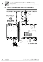
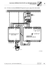
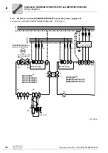
Connection of braking resistors
• Use
two tightly twisted leads or a 2-core shielded power cable
. Cable cross sec-
tion according to trip current I
F
of F16. The rated voltage of the cable must amount
to at least V
0
/V = 300 V / 500 V (in accordance with DIN VDE 0298).
• Protect the braking resistor (except for BW90-P52B) using a
bimetallic relay
(
→
wir-
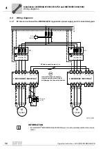
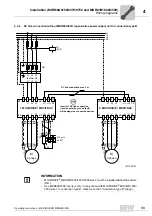
ing diagram for basic unit, power section and brake). Set the
trip current
according
to the
technical data of the braking resistor
. SEW-EURODRIVE recommends
using an overcurrent relay from trip class 10 or 10A in accordance with EN 60947-4-
1.
• For braking resistors of the
BW...-T / BW...-P
series, the
integrated temperature
switch/overcurrent relay can be connected using a 2-core shielded cable
as an
alternative
to a bimetallic relay.
•
Flat-type braking resistors
have internal thermal overload protection (fuse which
cannot be replaced). Install the
flat-type braking resistors
together with the appro-
priate
touch guard
.
4.1.9
Operating braking resistors
• The connection leads to the braking resistors carry a
high pulsed DC voltage
during
rated operation.
WARNING
The surfaces of the braking resistors get very hot when the braking resistors are
loaded with P
N
.
Risk of burns and fire.
• Choose a suitable installation location. Braking resistors are usually mounted on
top of the control cabinet.
• Do not touch the braking resistors.
Содержание MDR60A
Страница 2: ...SEW EURODRIVE Driving the world...
Страница 145: ......
Страница 146: ......
Страница 147: ......


