76
Operating Instructions – MOVIDRIVE® MDR60A/61B
6
Explanation of the parameters
MDR61B1600/2500 – Parameters
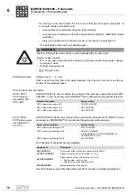
ble during an auto reset phase. If 5 errors occur that are reset by an auto-reset, no
more auto-resets are possible until:
– a manual reset is performed using the input terminal,
– a manual reset is performed using the serial interface (SHELL, DBGT60B, master
controller),
– there is a transition to 24 V backup mode, or the inverter is switched off.
Five automatic resets are then possible again.
• OFF: No auto reset.
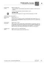
P842 Restart time
Setting range: 1 – 3 – 30 s
P842
is used to set the time to be waited between the time an error occurs and the ex-
ecution of an automatic reset.
P87x Process data description
P870 / P871 /
P872 Setpoint
description PO1 /
PO2 / PO3
P870
/
P871
/
P872
is used to define the content of the process output data words PO1/
PO2/PO3. This is necessary so MOVIDRIVE
®
B can allocate the appropriate setpoints.
P873 / P874 /
P875 Actual value
description PI1 /
PI2 / PI3
P873
/
P874
/
P875
define the content of the process input data words PI1/PI2/PI3. This is
necessary so MOVIDRIVE
®
B can allocate the appropriate actual values.
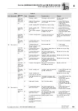
The following PI assignments are available:
See the "Fieldbus unit profile with parameter list" manual for a detailed explanation.
WARNING
Risk of crushing if the motor starts up automatically after an auto reset.
Severe or fatal injuries.
• Do not use auto reset with drives where an automatic restart represents a danger
to people or units.
• Perform a manual reset.
Setpoint description
Factory setting
P870 Setpoint description PO1
CONTROL WORD 1
P871 Setpoint description PO2
NO FUNCTION
P872 Setpoint description PO3
NO FUNCTION
Actual value description
Factory setting
P873 Actual value description PI1
STATUS WORD 1
P874 Actual value description PI2
OUTPUT CURRENT
(LINE CURRENT OF THE REGENERATIVE
POWER SUPPLY UNIT)
P875 Actual value description PI3
NO FUNCTION
Assignment
Description
NO FUNCTION
The content of the process input data word is 0000
hex
.
OUTPUT CURRENT
Present output current of the system in % of I
N
.
ACTIVE CURRENT
Present active current of the system in % of I
N
:
•
Positive sign = motor current
•
Negative sign = regenerative current
STATUS WORD 1
Status information of the inverter
P
i
f
kVA
Hz
n
Содержание MDR60A
Страница 2: ...SEW EURODRIVE Driving the world...
Страница 145: ......
Страница 146: ......
Страница 147: ......


