108
Operating Instructions – MOVIDRIVE® MDR60A/61B
12
Electrical connection
Installation (MDR60A1320-503-00)
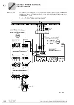
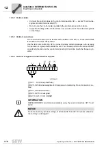
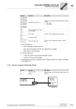
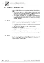
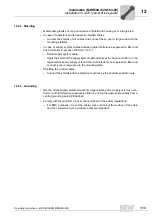
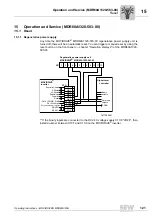
Wiring diagram
The following circuit diagram is a circuit recommendation. Special requirements for the
application, such as the integration of a PLC, may require changes to the connection of
contacts X2:1 ... X2:12.
1. ... 6.
→
Section "Notes on wiring diagram"
1877205131
L1
L2
L3
PE
F11 F12 F13
K11
(AC3)
NF...
L1
L2
L3
L1' L2' L3'
®
®
4
5
6
3
8
7
+R
PE
X1:
X4:
X2:
9
8
X3:
PE L1
L2
L3
PE
W
-R
PE
max. 5 m
-UZ +UZ
Incorrect DC link connection
(reverse polarity, ground fault) will
damage the connected deevices!
Never connect the
power connectors
of the inverter!
V
U
1
2
MOVIDRIVE
MDR60A1320-503-00
+
_
L1 L 2 L3
Control electronics
7 8 9 10 11 12
X2:
Relay contacts
X2:
2
1
4
3
ext.
OFF
ext. ON
RESET
ext. ON
RESET
4
5
6
3
8
7
+R
PE
X1:
X4:
X2:
9
8
X3:
PE L1
L2
L3
PE
W
-R
PE
BW... l
acts on K11
-UZ +UZ
V
U
1
2
Pre-charge
Observe the correct setting of
the voltage selection switch
400 V = 380 - 415 V
460 V = 440 - 480 V
500 V = 500 V
®
max. 5 m
1.
2.
3.
4.
6.
MOVIDRIVE / MOVITRAC
MOVIDRIVE / MOVITRAC
®
®
Inhibit
A1
A2
SKS
1 2 3
do not
connect!
Regeneration
Содержание MDR60A
Страница 2: ...SEW EURODRIVE Driving the world...
Страница 145: ......
Страница 146: ......
Страница 147: ......

