116
Operating Instructions – MOVIDRIVE® MDR60A/61B
13
Ready signal
Startup (MDR60A1320-503-00)
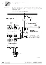
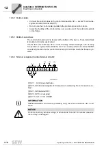
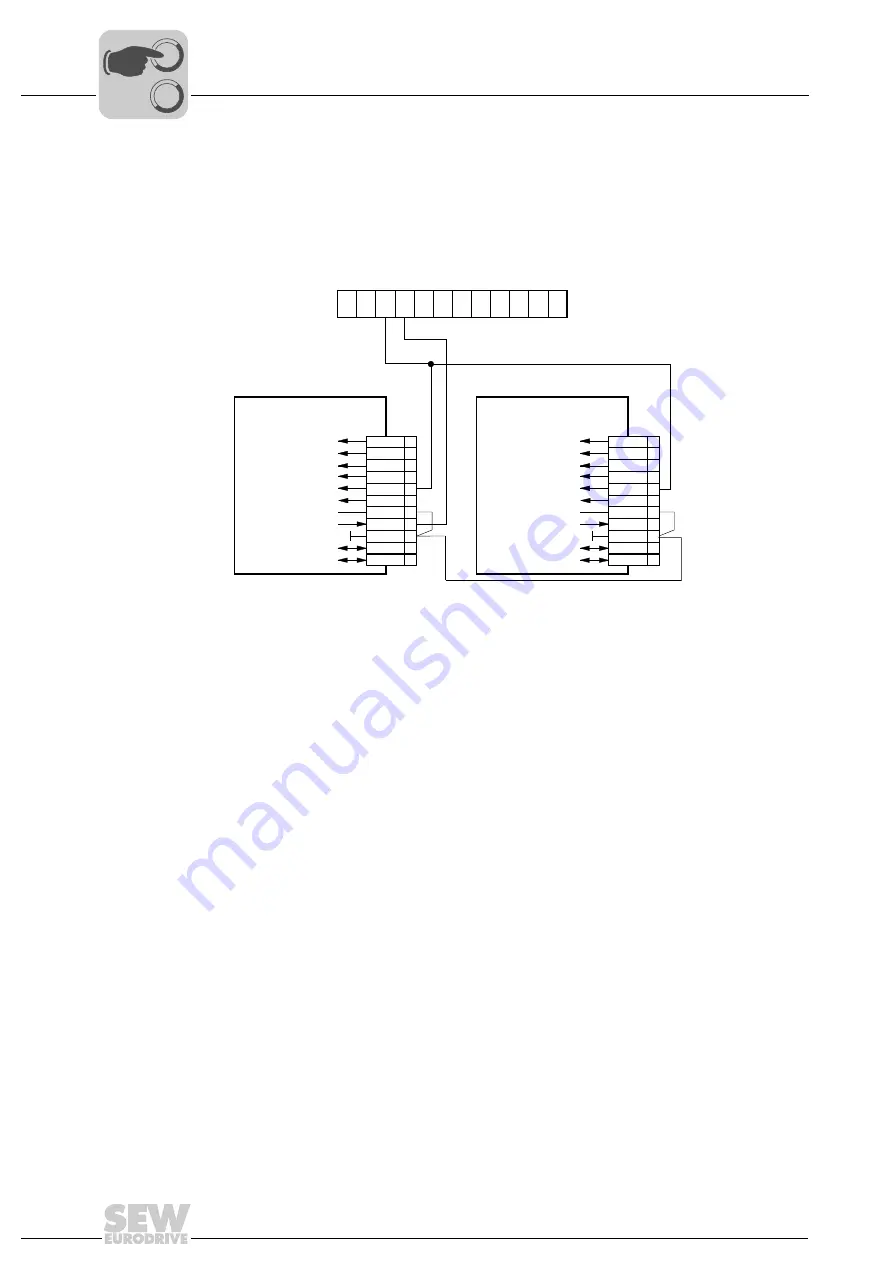
13.2 Ready signal
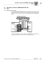
The following figure shows how the ready signal (ready) from the regenerative power
supply unit must be connected to the "Power supply system on" binary input of the in-
verter.
1877280523
X13:
X2:
X13:
DIØØ
DIØ1
DIØ2
DIØ3
DIØ4
DIØ5
DCOM
VO24
DGND
ST11
ST12
DIØØ
DIØ1
DIØ2
DIØ3
DIØ4
DIØ5
DCOM
VO24
DGND
ST11
ST12
1
2
3
4
5
6
7
8
9
10
11
1
2
3
4
5
6
7
8
9
10
11
Ref. potential binary signals
Ref. potential binary signals
Enable/stop
Enable/stop
/Contr. inhibit
/Contr. inhibit
CW/stop
CW/stop
CCW/stop
CCW/stop
Ref. X13:DIØØ...DIØ5
Ref. X13:DIØØ...DIØ5
DC+24 V output
DC+24 V output
Error reset
Error reset
RS-485 -
RS-485 -
RS-485+
RS-485+
inverter
MOVIDRIVE®
MOVIDRIVE
inverter
®
12
11
10
9
8
7
6
5
4
3
2
1
MOVIDRIVE® MDR60A1320-503-00
Regenerative power supply unit
Power on
Power on
0
0
I
Содержание MDR60A
Страница 2: ...SEW EURODRIVE Driving the world...
Страница 145: ......
Страница 146: ......
Страница 147: ......

