Operating Instructions – MOVIDRIVE® MDR60A/61B
19
3
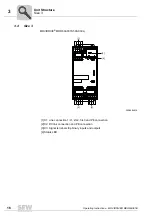
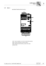
Size 7
Unit Structure
3.7
Size 7
MOVIDRIVE
®
MDR61B1600-503-00/L and MDR2500-503-00/L
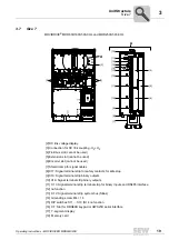
[2] DC link voltage display
[3] Connection for DC link coupling -U
Z
+U
Z
[4] Fieldbus slot (cannot be used)
[5] Extension slot (cannot be used)
[6] Encoder slot (cannot be used)
[7] Shield clamp for signal cables
[8] X17: Signal terminal strip for safety contacts for safe stop
[9] X10: Signal terminal strip binary outputs
[10] X16: Signal terminal strip binary outputs
[11] X13: Signal terminal strip terminal strip for binary inputs and RS485 interface
[12] no function
[13] X12: Signal terminal strip system bus (SBus)
[14] Grounding screw M4 × 14
[15] DIP switches S11 ... S13 (S14 no function
[16] XT: Slot for DBG60B keypad or UWS21B serial interface
[17] 7-segment display
[19] Memory card
A
[7]
[8]
[9]
[10]
[11]
[12]
[13]
[4]
[5]
[6]
[14]
[15]
[16]
[17]
[19]
A
[3]
[3]
[2]
Содержание MDR60A
Страница 2: ...SEW EURODRIVE Driving the world...
Страница 145: ......
Страница 146: ......
Страница 147: ......


