


Manual – IPOSplus®
337
23
Set commands
Assembler – Commands
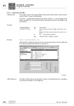
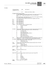
ANALOG INPUTS
-10 V ... 0 ... +10 V = -10000 ... 0 ... 10000
H+0
Voltage value analog input 1 [mV]
H+1
Voltage value analog input 2 [mV]
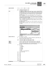
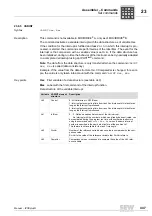
CAM
The
GETSYS H = CAM
command simulates a cam controller. Using the GETSYS
command, a standard cam controller with 1 output per cam can be used per drive.
With MOVIDRIVE
®
units, you can use an extended cam controller with 8 outputs.
Hxx is the first variable of a data structure (CamControl). The bit with the highest
significance (bit 31) is used in Hxx to decide which cam controller the GETSYS
command refers to.
Bit 31 = 0: Standard cam controller (all MOVIDRIVE
®
units). The GETSYS com-
mand activates the cam controller. The cams are formed once when the GETSYS
command is processed. If the standard cam controller is to process cyclically, the
command must be called up cyclically.
Bit 31 = 1: Extended cam controller with technology option and CFC or SERVO
mode). The GETSYS command activates the cam controller, the cams are formed
cyclically in the background.
The structure of the variables depends on whether the standard or expanded cam
controller is called.
The data structure is described in section "Position Detection and "Positioning/cam
controllers".
515353867
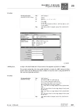
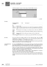
ANALOG OUTPUTS
+/- 10 V correspond to +/- 10000
H
The variable in the GETSYS H = ANALOG OUTPUTS command defines the
beginning of the following variable structure.
H+0
Contains the voltage value of analog output 1 (AO1)
H+1
Contains the voltage value of analog output 1 (AO2)
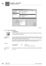
TIMER 0
Loads the current value of timer 0 [ms], identical to system variable H489
TIMER 1
Loads the current value of timer 1 [ms], identical to system variable H488
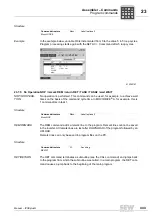
PO-DATA
Reads the PO data buffer (data sent from the master to the unit). 3 PO or 10 PO
data items are read depending on the number of PO data items.
H+0
Bus type
0 = reserved
1 = TERMINAL
2 = RS-485
3 = Fieldbus
4 = reserved
5 = SBus
8 = SBus 2 (only MOVIDRIVE
®
B)
H+1
Number of PO data
H+2
H+3
H+4
H+5
H+6
H+7
H+8
H+9
H+10
H+11
PO1
PO2
PO3
PO4
PO5
PO6
PO7
PO8
PO9
PO10
DC-VOLTAGE
DC link voltage [V]
P
i
f
kVA
Hz
n
P
i
f
kVA
Hz
n


