


66
Manual – IPOSplus®
6
Referencing
Position Detection and Positioning
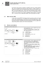
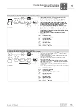
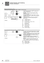
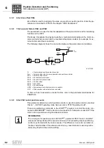
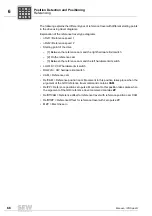
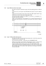
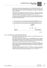
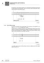
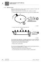
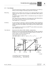
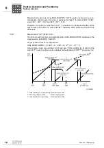
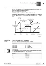
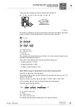
The following explains the different types of reference travel with different starting points
in the drive using travel diagrams.
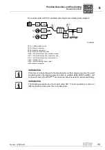
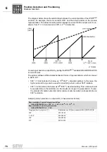
Explanation of the reference travel type diagrams
• nRef1 =Reference speed 1
• nRef2 =Reference speed 2
• Starting point of the drive
– [1] Between the reference cam and the right hardware limit switch
– [2] On the reference cam
– [3] Between the reference cam and the left hardware limit switch
• LHWLS = CCW hardware limit switch
• RHWLS = CW hardware limit switch
• CAM = Reference cam
• RefCAM = Reference position cam: Movement to this position takes place when the
argument of the GO0 reference travel command contains
CAM
.
• RefZP = Reference position zero pulse: Movement to this position takes place when
the argument of the GO0 reference travel command contains
ZP
.
• RefOffCAM = Reference offset for reference travel with reference position cam CAM
• RefOffZP = Reference Offset for reference travel with zero pulse ZP
• MZP = Machine zero
P
i
f
kVA
Hz
n
P
i
f
kVA
Hz
n


