


Manual – IPOSplus®
69
6
Referencing
Position Detection and Positioning
6.6.4
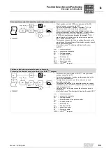
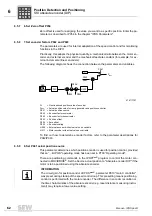
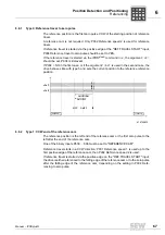
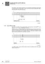
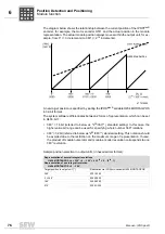
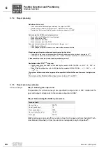
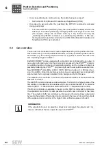
Type 3: CW limit switch
The reference position is the first zero pulse to the left of the CW limit switch.
The setting "Left end of the CW limit switch" is not important because after reference
travel, the drive could be located in the switch hysteresis of the limit switch and the error
"29 Limit switch reached" could occur sporadically once the reference travel is complete.
A reference cam is not required.
Reference travel starts in a CW direction. P901 Reference speed 1 is used up to the fall-
ing edge of the CW limit switch, then P902 Reference speed 2 is used.
If reference travel is started via the positive edge at the "REF.TRAVEL START" input,
P904 Reference travel to zero pulse should be set to YES.
If the reference travel is started via the IPOS
plus®
command
Go0
, you have to set the
argument
"ZP"
.
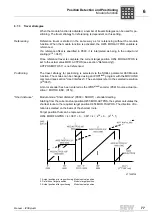
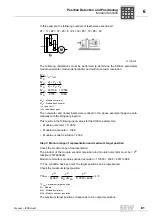
6.6.5
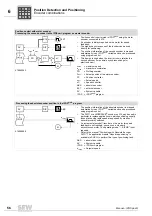
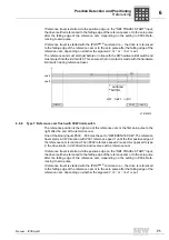
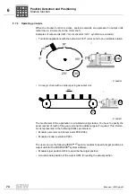
Type 4: CCW limit switch
The reference point is the first zero pulse to the right of the CCW limit switch.
The setting "Right end of the CW limit switch" is not important because after reference
travel, the drive could be located in the switch hysteresis of the limit switch and the error
"29 Limit switch reached" could occur sporadically once the reference travel is complete.
A reference cam is not required.
Reference travel starts in a CCW direction; P901 Reference speed 1 is used up to the
falling edge of the CCW limit switch, then P902 Reference speed 2 is used.
If reference travel is started via the positive edge at the "REF.TRAVEL START" input,
P904 Reference travel to zero pulse should be set to YES.
476758667
n
R
e
f
1
n
R
e
f
2
RHWL
S
RHWL
LHWL
S
[
1
]
[
1
]
[
3
]
[
2
]
R
e
fZ
P
R
e
f
M
Z
P
Z
R
e
f
O
ffZ
P
Z
R
P
i
f
kVA
Hz
n
P
i
f
kVA
Hz
n


