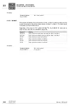


324
Manual – IPOSplus®
23
Positioning commands
Assembler – Commands
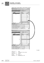
If the software limit switches have been set via parameter P920/P921, the software limit
switches are only monitored once reference travel is complete.
If the drive is not connected to an absolute or Hiperface
®
encoder, the reference point
is lost after an error message occurs and the drive has to be RESET.
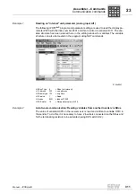
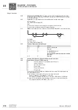
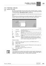
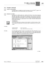
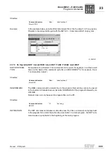
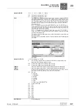
Structure
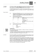
INFORMATION
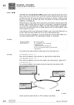
For type 3 and 4 and for the
CAM
setting, the drive must be referenced and positioned
right next to the hardware limit switch. For hoist applications and the lower reference
point in particular, when the drive is positioned to the lower point, it can collide with the
hardware limit switch at the slightest overshoot. The same danger applies when the
holding brake is released.
One way to prevent this from happening is to position the drive once reference travel
is complete so that the drive is positioned a sufficient distance away from the hardware
limit switch ( approximately 0.5 ... 1 motor revolution) .
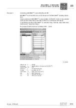
INFORMATION
If a waiting referencing command is interrupted by withdrawing the "/controller inhibit",
the error code 39 (reference travel) is set.
The axis does not start up once the signal has been restored. The IPOS
plus®
program
stops at this command.
A reset must be performed (binary input, fieldbus, SHELL ...). The IPOS
plus®
program
starts at the beginning of the first statement.
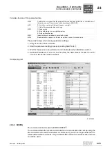
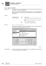
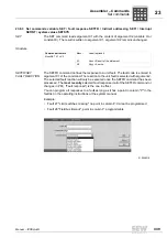
Command structure
Mxxx GO0 X1
Mxxx: Label (optional)
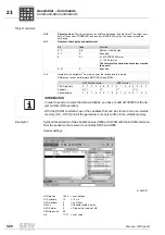
X1: Type of reference travel
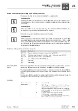
P
i
f
kVA
Hz
n
P
i
f
kVA
Hz
n


