


PY Manual
Copyright © 2006 SANYO DENKI
AMERICA
, Inc.
58
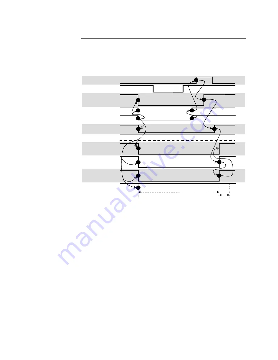
If an error occurs during operation, the amplifier signals the alarm and stops motion.
When the cause of the alarm is corrected and the amplifier alarm is reset, normal
operation can continue. The following timing diagram defines the sequence of operation
during a stop following an alarm and the restart after it is reset.
Notes:
1.
During an internal alarm condition, opening the “Interlock” has no effect. However,
release it before inputting “Start Ready”.
2.
This value can be changed to 0mS by setting the “Holding Brake Excitation Timing”
to “0” (Mode 1, Page 13). The current is limited by the sequence current limit value
for 300mS. The default value for the sequence current limit (SILM) is 120%. It may
be change in Mode 1, Page 12.
Stop and
recovery due to
an internal error
Start Ready ON (external switch)
Emergency Stop (EMR)
Main Circuit Power Supply (R,S,T)
Dynamic Brake
Holding Brake Excitation
Timing Output (HBON)
Start Ready Complete
Output (SRDY)
Motor Excitation
Contact Open
Amplifier Ready Output (RDY)
On
Off
On (Operating)
Servo ON (SON)
Command
On
On
On
300 msec
Command is Ineffective (Forced to Zero)
Off (Brake Engaged)
Internal Fault (ALM)
¦
§
¨
©
Artisan Technology Group - Quality Instrumentation ... Guaranteed | (888) 88-SOURCE | www.artisantg.com