Tel: 886. 909 602 109 Email: [email protected]
www.salukitec.com
85
After changing the settings, you need to click
to finish this configuration. Otherwise, the
settings are void.
12. Data Buffer Configuration
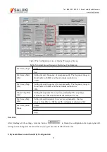
The data buffer configuration is shown in the red box in Fig.71. The details of configuration are shown in Table 13.
Fig.71 The Configuration Area of Data Buffer
Table 13. Data Buffer Configuration Options
Buffer 1
Users can choose the following value, the X/Y/R/θ of signal or
signal harmonic, the ADC1/ADC2/ADC3/ADC4 of AUX_ADC
input, noise, frequency, the E1/E2/E3/E4 of equation and C1/C2.
Buffer 2
Buffer 3
Buffer 4
Step Time (ms)
Set the step time manually. The time range is 1ms to
100s, the minimum resolution is 1 ms.
Length
Set the data length manually. The length range is 1 to
16384, the minimum resolution is 1.
Int/Ext
Int
Ext
Single/Loop
Single
Loop


