Tel: 886. 909 602 109 Email: [email protected]
www.salukitec.com
78
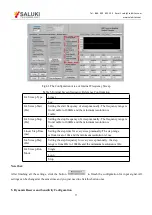
The configuration area of Dynamic Reserve and Sensitivity is in the red box in Fig.64. The details of configuration are
listed on the Table 6.
Fig.64 The Configuration Area of Dynamic Reserve and Sensitivity
Table 6. Dynamic Reserve and Sensitivity Configuration
Dynamic Reserve
Low Noise
Normal
High Reserve
Sensitivity
1nV/fA
200nV/fA
50μV/pA
10mV/nA
2nV/fA
500nV/fA
100μV/pA
20mV/nA
5nV/fA
1μV/pA
200μV/pA
50mV/nA
10nV/fA
2μV/pA
500μV/pA
100mV/nA
20nV/fA
5μV/pA
1mV/nA
200mV/nA
50nV/fA
10μV/pA
2mV/nA
500mV/nA
100nV/fA
20μV/pA
5mV/nA
1V/μA
Note that:
After finishing all the settings, click the button
to finish the configuration for input signal.
All settings can be changed at the same time and you just need to click this button once.
After changing the settings, you need to click
to finish this configuration. Otherwise, the
settings are void.


