Tel: 886. 909 602 109 Email: [email protected]
www.salukitec.com
74
Fig.60 Software Connection Succeeds
3. Input Configuration
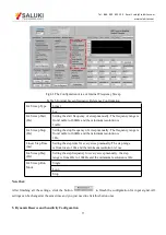
The program configuration area of input signal is as shown in the red box in Fig.61. The details of the configuration are
listed on Table 3.
Fig.61 The Configuration Area of Input Signal
Table 3. Input Configuration
Input Source
Single-Ended Voltage
Differential Voltage
Current


