background image

Setup and Operations Manual

SEE™ 

RVision   P/N 

660904-01  

Rev 1

Page 11

Connect the HiDef Connector to LOOK™

Plug the male DB9 connector of the QuickConnect cable to the female connector of 

the LOOK™ joystick controller with LCD. 

DO NOT apply power to the LOOK™ before mounting the camera!

Connect the LOOK™ to Power Source

Make sure the camera mount is secure before connecting power source to the 

LOOK™ joystick controller with LCD.

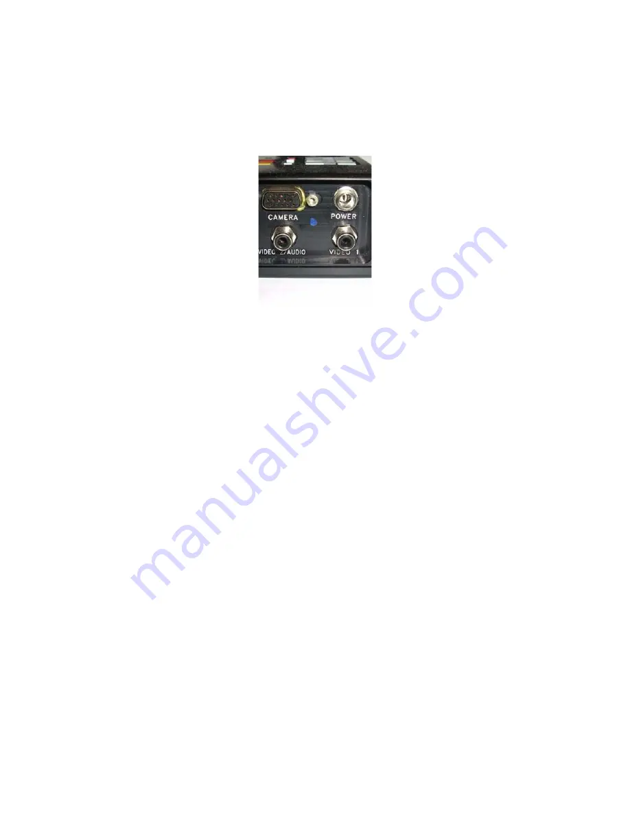
HiDef connector 

goes into “Camera” 

port, upper-left 

corner,

DO NOT plug the 

power source to 

the LOOK™ (shown 

here, upper-right 

corner) before 

mounting the cam-

era!

 Figure 14: HiDef connector

Содержание SEE

Страница 1: ...nt of State or the U S Bureau of Industry and Security U S Department of Commerce It is unlawful and strictly prohibited to export or attempt to export or otherwise transfer or sell any hardware or te...

Страница 2: ...e warranty See the back of this manual for a complete warranty liability and copyright statement CAUTION Please read this manual to avoid improper installation Careless operation of any RVision Pan Ti...

Страница 3: ...he LOOK Controller 10 Connect the HiDef Connector to LOOK 11 Connect the LOOK to Power Source 11 Attach QuickConnect to Breakout Adapter 12 Connect Adapter to PC 12 Install pSEE 12 Running the pSEE Ap...

Страница 4: ...A 5 Port A 6 Multicast A 6 Flow Control Mode A 6 Serial Port Configuration Unsupported A 6 Configuring the Video A 6 Encode A 7 Motion Detection A 8 Resolution A 8 Video Options and Changing Event Ac...

Страница 5: ...Download dialog box 15 Figure 18 Save As dialog box 16 Figure 19 pSEE zip zipped format 16 Figure 20 pSEE Customer Information dialog box 16 Figure 21 File Download Security Warning dialog box 17 Fig...

Страница 6: ...net Protocol Properties A 2 Figure 45 SEE IP Cable A 4 Figure 46 Network Configuration A 5 Figure 47 Video Configuration A 7 Figure 48 IP Video Login A 9 Figure 49 Live View video image feed A 10 Figu...

Страница 7: ...page functions 25 Table 6 Misc tab page functions 27 Table 7 Manual Commands tab page functions 28 Table 8 Titling tab page functions 29 Table 9 LCD status information 32 Table 10 Action on joystick...

Страница 8: ...viii RVision P N 660904 01 Rev 1 This page intentionally left blank...

Страница 9: ...wireless LAN The SEE can be used with a LOOK Controller existing legacy Closed Circuit TV CCTV systems third party encoders Digital Video Record ers DVRs video servers and other security management t...

Страница 10: ...l jurisdiction of either the U S Department of State or the U S Bureau of Industry and Security U S Department of Commerce It is unlaw ful and strictly prohibited to export or attempt to export or oth...

Страница 11: ...with pSEE Soft ware on page 15 for detailed installation and operation instructions Figure 2 Connecting the SEE to the SEE2PC Integration Tool Make sure the following is available RVision SEE2PC Inte...

Страница 12: ...EE Application on page 12 7 Connecting to Third Party Controllers on page 13 Mounting the QuickConnect Mount Cable to a Pole The SEE is shipped with a QuickConnect Mount Cable and the correct cable le...

Страница 13: ...Base the foot into QuickConnect Rails the shoe until there is a solid connection between their connectors Figure 4 Slide the camera foot into mount plates shoe 2 Tighten the security screw on the out...

Страница 14: ...EE2PC Integration Tool Attach the 15 pin male connector of the QuickConnect Cable to the SEE2PC female counterpart The SEE2PC integration tool is a multiple cable adapter configured with many indus tr...

Страница 15: ...RS422 camera Figure 7 RS422 to RS232 Adapter Connecting the RS 232 connector to a PC The pSEE application requires an RS 232 serial port be reserved on the PC The following USB to serial port adapter...

Страница 16: ...he power jack Figure 10 Connecting the Power Cable Plug NOTE Make sure that the collar of the power plug is fastened securely to the threads of the DC power jack The SEE camera performs a calibration...

Страница 17: ...e factory Contact sales rvisionusa com for additional information about customized cable Connectors The LOOK controller has four connectors located at the bottom of the unit as shown in Figure 11 Figu...

Страница 18: ...Figure 12 Connect power to LOOK Controller 2 Connect the power connector from a cigarette lighter to the DC adapter Refer to Figure 13 Figure 13 Connect power to the DC adapter WARNING Make sure that...

Страница 19: ...controller with LCD DO NOT apply power to the LOOK before mounting the camera Connect the LOOK to Power Source Make sure the camera mount is secure before connecting power source to the LOOK joystick...

Страница 20: ...g pSEE Software on page 15 for information on installing the pSEE application Running the pSEE Application Install the pSEE application as detailed in the Installing pSEE Software on page 15 Insert Hi...

Страница 21: ...ing criteria Transport RS232 RS422 or RS485 Protocol enhanced VISCA 1 or Pelco D2 Baud rate 2400 9600 57600 are supported Parity none Flow control Off Data bits 8 Stop bit 1 NOTE Contact techsupport r...

Страница 22: ...Page 14 RVision P N 660904 01 Rev 1 SEE Setup and Operations Manual This page intentionally left blank...

Страница 23: ...e mail To obtain the pSEE URL send an e mail to RVision at the following address techsupport rvisionusa com NOTE If the computer running pSEE is networked the network administrator may be required to...

Страница 24: ...top and then click Save Figure 18 Save As dialog box s Click the zipped file pSEE zip Figure 19 pSEE zip zipped format d The pSEE zipped directory is displayed Copy or drag the file pSEE msi on to the...

Страница 25: ...is displayed Click Run Figure 21 File Download Security Warning dialog box 5 The InstallShield Wizard is displayed Click Next Figure 22 pSEE Program dialog box 6 The Customer Information dialog box is...

Страница 26: ...60904 01 Rev 1 Figure 23 Customer Information dialog box 7 The Destination Folder dialog box is displayed Accept the default destination folder for installation or browse to the destination folder the...

Страница 27: ...gram dialog box is displayed Click Install Figure 25 Ready to Install Program dialog box 9 During installation the Installing pSEE dialog box is displayed Figure 26 Installation progress box 10 When t...

Страница 28: ...EE Tabbed Page Functions Tab Page Function Communication Communication between computer and the attached SEE camera Tilt Pan Zoom Controls the pan tilt and zoom function of the SEE camera This tab als...

Страница 29: ...Desktop icon 2 The Communication tab page is displayed Figure 29 Communication tab page 3 If an RVision pan tilt zoom device is connected to the PC running pSEE the Communication tab page displays the...

Страница 30: ...before connect ing pSEE will still sense the camera is RS232 because of the adapter Address COM port of the PC Number of video streams Not supported Discover Queries for available cameras on selected...

Страница 31: ...tical orientation of the SEE and the zoom function of the camera Figure 30 Pan Tilt Zoom tab page Table 4 lists the Pan Tilt Zoom tab page functions Table 4 Pan Tilt Zoom tab page functions Function D...

Страница 32: ...k Auto focus to be used Zoom In Narrow field of view Zoom Out Wide field of view Miscellaneous C T Not supported Illuminator Toggles NIR or visible illuminator if installed NIR mode must be on to see...

Страница 33: ...upper left corner of the Presets tab page 3 Click Get Current 4 Enter the desired pan and tilt speed 1 24 5 If the preset is to be used in a tour check Last preset in tour if it will be the final pre...

Страница 34: ...t 1 24 Tilt Speed Speed of vertical movement 1 24 Dwell Dwell time is the amount of time the SEE remains at the preset and includes travel time For example if it takes 1 second to travel to the preset...

Страница 35: ...tcet era Brakes Leave on Stabilization Toggle Turn video image stability off or on Corrects low frequency vibration EVI D 100 Emulation Not supported Inverted Select this option if the camera is mount...

Страница 36: ...ons Defaults Reset all options to factory setting defaults Do not use unless prompted by RVision support Retries Do not use a Auto NIR enabled at the factory unless illuminator is installed b Contact...

Страница 37: ...Loop Script Not supported Return Code Display device acknowledgement or system response to last command sent Table 8 Titling tab page functions Function Description Titling On Enable Title mode Text...

Страница 38: ...default is set to 1 using the Send Command field in the Manual Commands tab page enter the following command 88 30 AB FF where AB is the hexadecimal camera address As an example to set the camera ID...

Страница 39: ...NTSC or PAL video formats Joystick for pan tilt motion control and the camera s zoom control Keypad for entering commands Input output ports for connecting a camera power and video audio outputs Figu...

Страница 40: ...preset for one button recall Increase or decrease pan and tilt and preset scan speed Adjust for back lit conditions Table 9 LCD status information Display Description 687001XX Version of firmware Joy...

Страница 41: ...E RVision P N 660904 01 Rev 1 Page 33 Figure 37 is a photograph of the LOOK Controller keyboard Figure 37 LOOK Controller keypad Gear UP DN Function 1 2 Display HI LO Focus Near A F LED 2ND Shift Mode...

Страница 42: ...SEE Setup and Operations Manual Page 34 RVision P N 660904 01 Rev 1 This page intentionally left blank...

Страница 43: ...off when auto focus is off Toggle near infra red NIR low light mode black and white Press Mode M NOTE Cameras without illumina tors are configured for auto NIR Autofocus indication The green LED below...

Страница 44: ...nd 2 Tour continues to exe cute until the process is stopped manually with joystick movement Initiate Tour 5 sec ond interval between preset is factory default Simultaneously press FUNC TION 1 and FUN...

Страница 45: ...he LOOK single mode configuration uses two types of cables Table 13 lists these cables by RVision part number and description Table 12 LOOK Single mode connectors and their function Connectors Functio...

Страница 46: ...t the RCA type video cables are attached to the correct connector on the LOOK Figure 39 illustrates the cables connected to the LOOK Figure 39 Cables connected to the LOOK D sub HiDef female 15 pin Po...

Страница 47: ...In this procedures assume a factory default setting of 192 168 10 XXX The XXX digits vary between cameras To communicate with the camera you must set the computer s IP address to be a static IP other...

Страница 48: ...ton to view the Connection Properties page Figure 42 Connection Status 5 The Connection Properties page is displayed Select Internet Protocol TCP IP Figure 43 Connection Properties 6 The Internet Prop...

Страница 49: ...roller One to many controller connections Multicasting Automatic transmit rate control according to network condition Sensor and Alarm The SEE IP can send an Event Alarm System Connections The SEE IP...

Страница 50: ...SEE IP into a network with this address refer to the Setting up the Network Configuration section for detailed instructions Connecting the RJ45 connector to a PC The SEE IP connects to a PC through th...

Страница 51: ...figuration The IP Mode selection influences the availability of options in other categories Only the parameters allowed by the Fixed IP mode under Local are supported Local IP Mode Set Fixed IP local...

Страница 52: ...e chosen Serial Port Configuration Unsupported Using the Video Surveillance Serial Port window to manipulate SEE IP systems is not recommended Configuring the Video Video compression and setting actio...

Страница 53: ...60904 01 Rev 1 A 7 Figure 47 Video Configuration Encode Changing Bitrate Preference to Quality will enable Quality slider Bitrate Video compression set to Bitrate value entered Quality selected Video...

Страница 54: ...figuration This feature is not currently supported Frame rate Video frame rate can be limited by network band width Quality Preference must be set to Quality Bitrate Preference must be set to Bitrate...

Страница 55: ...able 14 will grant access to the suite of network parameters and video functions needed to setup and operate the SEE IP video surveillance system IP Video is a web page interface for guests users man...

Страница 56: ...age feed in the Live View web page Figure 49 Live View video image feed The image controls pictured on the right in Figure 49 will not work for viewers with Guest privilege Image Control For viewers g...

Страница 57: ...e configuration utilities if the Admin has granted viewers Manager privilege Manager users and the Admin will be admitted to Setup directly from the IP Video page after logging in Only viewers with Ma...

Страница 58: ...functions are grouped into the following categories System Video Network Event Preset User Functions and features shown in the Serial window are not supported System Configuration NOTE The System Conf...

Страница 59: ...k and administrator Video Standard NTSC or PAL signal type System ID Alphanumeric System ID to be transferred to remote software Current Time To update enter new date and time select Set Current Time...

Страница 60: ...A 14 RVision P N 660904 01 Rev 1 SEE Setting up the SEE IP Camera This page intentionally left blank...

Страница 61: ...lacement of the product by RVISION the choice as to which is in the exclusive discretion of RVISION The foregoing is in lieu of all other expressed warranties and RVISION does not assume or authorize...

Страница 62: ...or other device to which the camera is mounted to a motor vehicle or other mobile or stationary site Always install a security tether to the edge bolt of the camera This warranty does not cover adjust...

Страница 63: ...kg System Power Operating Voltage 12 to 30 VDC 500 ma 2A peak Command and Control RS232 RS422 IP optional Factory configured software selectable BAUD 2400 4800 9600 57 600 Software Selectable Factory...
Страница 64: ...N 660904 01 Rev 1 Housing Material Cast and Machined Aluminum Camera specs Optical Zoom 26X Digital Zoom 12X TV lines NTSC PAL 470 460 PEL count NTSC PAL 680 000 740 000 Light sensitivity 0 05 Lux NIR...

Отзывы: