


Magnum 2000/4000 is switched on and off with the foot switch (4) only.
On Magnum 2010/4010 and 2020/4020, the second operating speed
can be selected for sectioning, deburring and small thread cutting ope-
rations. To do this, with the machine running, slowly move switch (3)
from position 1 to position 2. With the contact lever (8), advance the
die head onto the rotating material.
After one or two threads have been cut, the die head will continue to
cut automatically. In the case of tapered pipe threads, the die head
opens automatically when the standard length of thread is reached.
When cutting extended threads or bolt threads, open the die head ma-
nually, with the machine running. Release pedal switch (4). Open quick
action hammer chuck, take out material.
Threads of unlimited length can be cut by reclamping the material, as
follows. When the tool holder approaches the machine housing during
the thread cutting process, release pedal switch (4) but do not open
the die head. Release the material and bring the tool holder and ma-
terial to the right-hand end-position by means of the contact lever.
Clamp material again, switch on machine again.
For pipe cutting operations, swing in the pipe cutter (18) and bring it
to the desired cutting position by means of the contact lever. The pipe
is cut by rotating the spindle clockwise.
Remove any burrs inside the pipe resulting from the cutting operation
with the pipe reamer (19).
To drain the cooling lubricant: Take off the flexible hose of the tool
holder (7) and hold it into a container. Keep the machine running until
the oil tray is empty. Or: Remove screw plug (25) and drain trough.
3.4. Production of nipples and double nipples
Use REMS Nippelfix (automatic internal clamping) or REMS Nippel-
spanner (internal clamping) for threading nipples. Ensure that both
sides of the pipe are deburred inside. Always slide the pipe up to the
end of the clamping section.
To clamp the piece of pipe (with or without thread) with the REMS Nip-
pelspanner, use a screwdriver and turn the spindle to expand the head
of the Nippelspanner. Expand only with attached piece of pipe, other-
wise damage will arise.
Do not cut nipples with REMS Nippelfix and REMS Nippelspanner
shorter than is permitted by the appropriate standard.
3.5. Producing left-handed threads
For left-handed threads only the REMS Magnums 2010, 2020, 4010
and 4020 are suitable. The die head in the tool set holder has to be
off-set e.g. by using a M12x40 screw in order to cut left-handed thre-
ads, otherwise the lifting and the start-cutting can be damaged. Set
the switch to position “R”. Change the hose connections at the coo-
lant pump or for shut of the coolant pump briefly. Alternatively use a
switch valve (Art.No. 342080, accessory), attached to the machine.
With the lever on the switch valve (Fig. 9) the direction of flow on the
coolant pump is reversed.
4. Service
Disconnect the plug from the mains before starting any repairs! Such work
must be carried out only by experts and trained personnel.
4.1. Maintenance
The machine is maintenance free. The gearbox operates in a sealed-
off oilbath and therefore needs no lubrication.
4.2. Inspection / Servicing
The motor of the Tornado 2000 / Magnum 2000 / 4000 is equipped
with carbon brushes. These wear out and therefore need checking
from time to time, and, if necessary, changing. Loosen by about 3 mm
(
1
/
8
”) the 4 screws of the motor cap and remove both caps from the
motor. See also point 6: Actions in case of trouble.
eng
eng
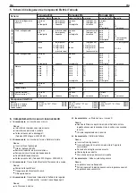
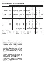
5. Machine Wiring and Electrical Components Tornado
RW 345
REMS
CA 10 C 58751 * FT22V
REMS
T 5300
REMS
Machine Wiring
Wire colour/No.
brown
blue
green/yellow
brown
blue
green/yellow
red
red
brown
blue
green/yellow
black
2
black
5
black
6
black
4
black
3
black
1
brown
blue
brown
blue
green/yellow
Tornado 2000
Tornado 2010
Tornado 2020
Terminal
2 (emergency stop)
2 (emergency stop)
W
casing
2 (motor protection)
1 (emergency stop)
W
casing
1 (emergency stop)
↓
13 (button)
14 (button)
↓
1 (motor protection)
1
3
W
casing
4
8
10
6
5
2
5
12
1
3
W
casing
Wire colour/No.
brown
blue
green/yellow
brown
blue
green/yellow
red
red
brown
blue
green/yellow
black
1
black
2
black
3
black
4
black
5
black
6
green/yellow
brown
blue
brown
blue
green/yellow
Terminal
2 (emergency stop)
2 (emergency stop)
W
casing
2 (motor protection)
1 (emergency stop)
W
casing
1 (emergency stop)
↓
13 (button)
14 (button)
↓
1 (motor protection)
R
S
W
casing
U
1
V
1
W
1
U
2
V
2
W
2
W
casing
C
1
C
2
R
S
W
casing
Wire colour/No.
brown
black
black
blue
green/yellow
black
1
black
2
black
3
black
4
black
5
green/yellow
red
red
black
1
black
2
black
3
black
4
black
5
green/yellow
black
1
black
2
black
3
black
4
black
5
black
6
black
7
black
8
green/yellow
brown
blue
green/yellow
Terminal
1
3
5
A1
W
casing
2
4
6
14
2 (emergency stop)
W
casing
5
→
1 (emergency stop)
13
→
A2
L
1
L
2
L
3
4
5
W
casing
U
1
V
1
W
1
U
2
V
2
W
2
7
8
W
casing
L
1
L
2
W
casing
Mains line
Connecting line
Inner line
Connecting line
Motor
Resistor
Capacitor
Electric pump
(Machine model “ T”)
Motor
Cam switch
Foot switch
Capacitor
Foot switch
Gearbox
Base
RW 342
REMS
CA 10 C 58761 * FT22V
REMS
T 5300
REMS
MP 35/100/330
REMS
RW 343
REMS
CA 10 D-U277 * 01 FT22V
REMS
T 5400
REMS
Electrical Components


