


7
Contr
oller system settings
7-18
■
Origin sequence
‹
ORGORD
›
This parameter sets the order of return-to-origin operation using the axis number (1 to 6).
Axes perform return-to-origin operation in order from the left end. Axes that are not set finally perform return-to-origin
operation at the same time. When this parameter is initialized, "312456" is set.
CAUTION
When performing return-to-origin of three or more axes with the return-to-origin method set at the stroke end
method, the emergency stop may be activated.
At this time, change the stroke end return-to-origin method to simultaneous two axes or return-to-origin of each axis.
NOTE
•
Perform return-to-origin operation from an axis that may interfere with a peripheral device.
• This order includes the robot axis and axillary axis.
When different position detection methods (absolute specifications or incremental specifications) are mixed in
one robot, the order of return-to-origin operations may vary depending on the return-to-origin method.
Example:
Robot axis configuration:
Axis 1, axis 2, axis 3, axis 4
Return-to-origin order setting: 312456
Position detection method of each axis: Axis 1, axis 2 Incremental specifications
Axis
3,
axis
4
Absolute specifications
1. Return-to-origin operations of only the absolute type axes are performed.
Return-to-origin operations of only the absolute type axes are performed from the left end of the return-to-
origin order setting in order.
3
1
2
4
5
6
Axis 3 operation
Axis 1 cancel
Axis 2 cancel
4 operation
Axis 5 cancel
Axis 6 cancel
2. Return-to-origin operations of only the incremental type axes are performed.
Return-to-origin operations of only the incremental type axes are performed from the left end of the return-
to-origin order setting in order.
3
1
2
4
5
6
Axis 3 cancel
Axis 1 operation
Axis 2 operation
Axis 4 cancel
Axis 5 cancel
Axis 6 cancel
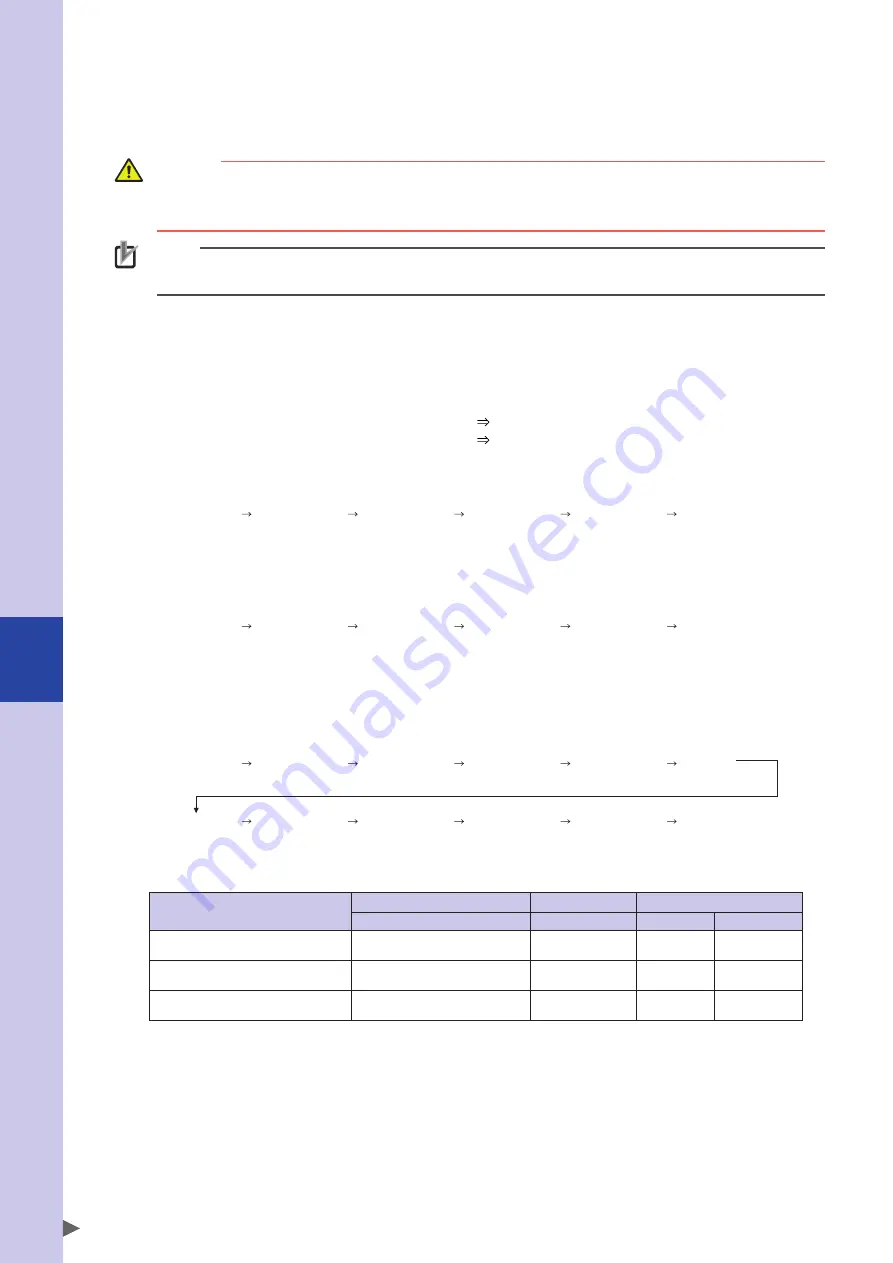
3. Return-to-origin operations of both the absolute type and incremental type axes are performed.
First, return-to-origin operations of the absolute type axes are performed from the left end of the return-to-
origin order setting in order.
Subsequently, return-to-origin operations of the incremental type axes are performed in the same manner.
3
1
2
4
5
6
Axis 3 operation
Axis 1 cancel
Axis 2 cancel
Axis 4 operation
Axis 5 cancel
Axis 6 cancel
3
1
2
4
5
6
Axis 3 cancel
Axis 1 operation
Axis 2 operation
Axis 4 cancel
Axis 5 cancel
Axis 6 cancel
The actual example of return-to-origin operation is shown below.
Programming box operation
PGM execution
IO operation
Key operation
Command *1
Input port
DI17 mode *2
Absolute specifications only
Impossible (possible by-axis)
ORIGIN 0, 2
DI17
ABS
Incremental specifications only
Impossible (possible by-axis)
ORIGIN 0, 1
DI14
ABS
Both specifications at the same time
"ALL"
ORIGIN 0, 0
DI17
ABS/ORG
*1 For details about ORIGIN command, refer to the YRCX programming manual.
*2 This is the DI17 mode setting of the control parameters.
Содержание R6YXC1000
Страница 1: ...7 6HULHV DW 1R 1 5 5RERW RQWUROOHU 86 5 6 0 18 6 5 5RERWV 5 6HULHV...
Страница 2: ......
Страница 10: ......
Страница 40: ......
Страница 42: ......
Страница 46: ......
Страница 48: ......
Страница 54: ......
Страница 56: ......
Страница 64: ......
Страница 80: ......
Страница 82: ......
Страница 102: ......
Страница 108: ......
Страница 110: ......
Страница 136: ......
Страница 168: ......
Страница 170: ......
Страница 174: ...8 Periodic inspection 8 4...
Страница 176: ......
Страница 182: ......
Страница 256: ......
Страница 258: ......
Страница 259: ......
Страница 260: ...DW 1R 1 XWKRUL HG LVWULEXWRU 3ULQWHG LQ XURSH...