background image

78

Parameter Verification

Section 3-8

3-8

Parameter Verification 

After downloading the parameters to a device, the user must perform parame-
ter verification to check whether the parameters entered by the user were cor-
rectly downloaded to the device. The user must perform this verification for
safety devices.

3-8-1

Device Parameter Verification

Verify the parameters using any of the following methods after downloading
the parameters to devices. This function is enabled only when the Network
Configurator is online.

With Network Configurator Ver. 2.0

@

 or higher, multiple devices can be

selected and verified all at once. 

1.

Select a device, and then select 

Device - Parameter - Verify

 from the

menu bar.

2.

Select a device, and then click the 

Verify Parameter

 Button on the toolbar.

3. Select a device, and then right-click the device and select 

Parameter


-

Verify

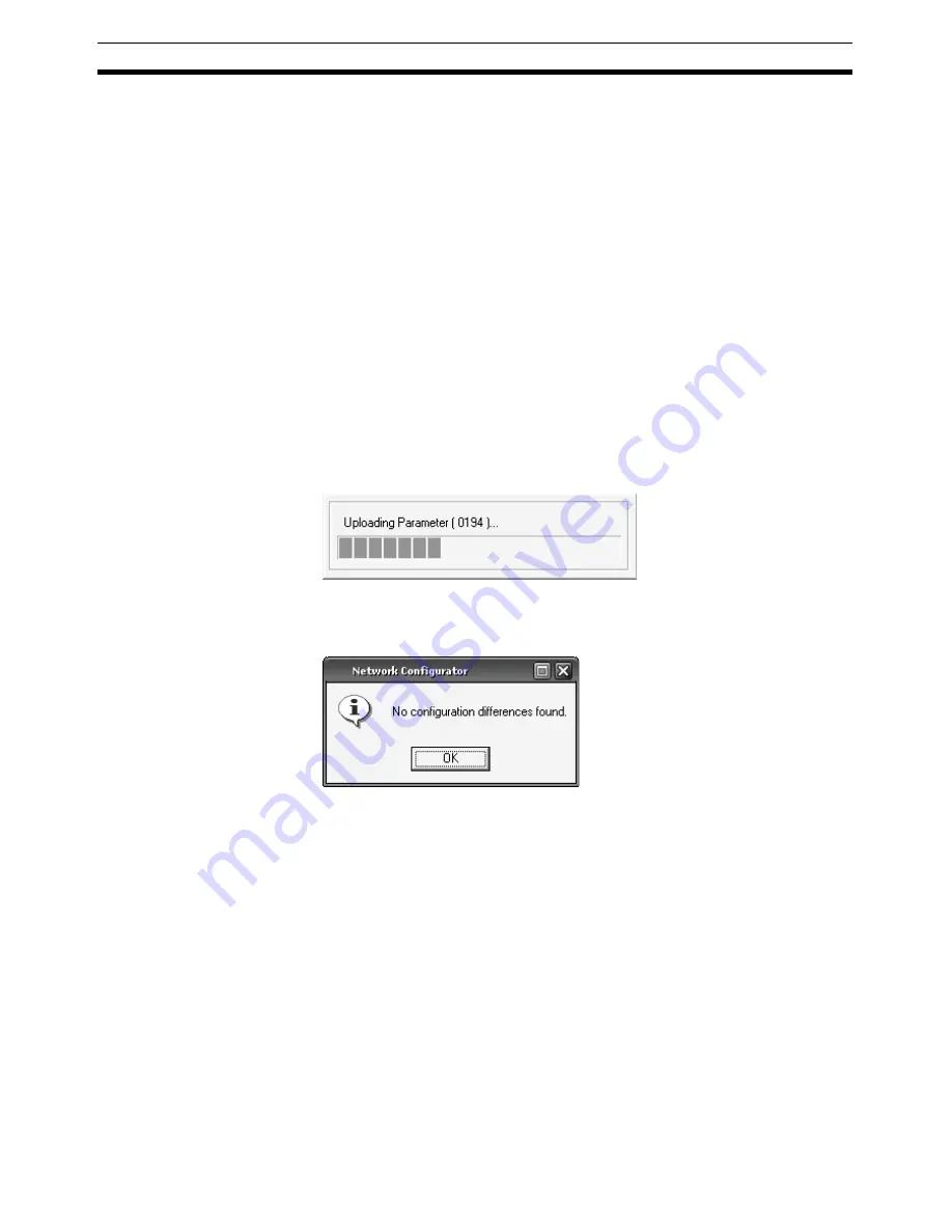
The device parameters will be uploaded.

First, the Network Configurator itself checks if the uploaded parameters are
different from the parameters in the virtual network. If there are no differences,
the following dialog box will be displayed. 

If you click the 

OK

 Button, the uploaded parameters will be displayed.

Содержание DeviceNet Safety

Страница 1: ...SYSTEM CONFIGURATION MANUAL Cat No Z905 E1 07 DeviceNet Safety...

Страница 2: ......

Страница 3: ......

Страница 4: ......

Страница 5: ...DeviceNet Safety System Configuration Manual Revised July 2009...

Страница 6: ...iv...

Страница 7: ...italized in this manual The word Unit is also capitalized when it refers to an OMRON product regardless of whether or not it appears in the proper name of the product The abbreviation PLC means Progra...

Страница 8: ...electronic photocopying recording or otherwise without the prior written permission of OMRON No patent liability is assumed with respect to the use of the information contained herein Moreover because...

Страница 9: ...twork Configurator 35 3 1 Network Configurator Startup and Main Window 37 3 2 Menu List 40 3 3 Connecting to the Network 48 3 4 Creating a Virtual Network 54 3 5 Saving and Reading Network Configurati...

Страница 10: ...nnection Status Tables 220 8 2 Errors When Downloading 225 8 3 Errors When Resetting 228 8 4 Errors When Changing Modes 229 8 5 Errors That Can Be Found Using the Connection Check Function 230 SECTION...

Страница 11: ...ix TABLE OF CONTENTS Appendix 277 Glossary 333 Index 335 Revision History 339...

Страница 12: ......

Страница 13: ...on Manual W267 This manual describes the construction and connection of a DeviceNet network It provides detailed information on the installation and specifications of cables connectors and other perip...

Страница 14: ...xii...

Страница 15: ...AS DETERMINED THAT THE PRODUCTS WILL SUITABLY MEET THE REQUIREMENTS OF THEIR INTENDED USE OMRON DISCLAIMS ALL OTHER WARRANTIES EXPRESS OR IMPLIED LIMITATIONS OF LIABILITY OMRON SHALL NOT BE RESPONSIBL...

Страница 16: ...that the uses listed may be suitable for the products Outdoor use uses involving potential chemical contamination or electrical interference or conditions or uses not described in this manual Nuclear...

Страница 17: ...nfirm actual specifications of purchased products DIMENSIONS AND WEIGHTS Dimensions and weights are nominal and are not to be used for manufacturing purposes even when tolerances are shown PERFORMANCE...

Страница 18: ...xvi...

Страница 19: ...xvii PRECAUTIONS 1 Intended Audience xviii 2 General Precautions xviii 3 Safety Precautions xx 4 Precautions for Safe Use xxi...

Страница 20: ...mechanisms This manual provides information for programming and operating the Unit Be sure to read this manual before attempting to use the Unit and keep this man ual close at hand for reference durin...

Страница 21: ...ystems Functional Safety of Electrical Electronic Programmable Electronic Safety related Systems Complying with Laws and Regulations The safety devices conform to the relevant regulations and standard...

Страница 22: ...previous configuration data Safety functions may be impaired and serious injury may occasionally occur Before connecting a device to the network configure the appropriate node address and the baud rat...

Страница 23: ...s close to power supplies Mounting Confirm the operating suggestions provided in the operation manual for each product before installation and mounting Wiring Use the following wires to connect extern...

Страница 24: ...ng requirements The secondary circuits of the DC power supply must be isolated from the primary circuit by double insulation or reinforced insulation The DC power supply must satisfy the requirements...

Страница 25: ...ch replacement Supported Supported Supported Supported Device connection configuration dis play Supported Supported Supported Supported Saving and reading design data for individual networks in files...

Страница 26: ...p between NE1A series Controller unit versions and the revisions Checking the Unit Version on the Product Nameplate The unit version Ver is listed near the lot number on the nameplate of the products...

Страница 27: ...Select Property from the menu The Controller s Property Window will be displayed The Controller s model number device name and revision are displayed in the Property Window The NE1A series Controllers...

Страница 28: ...differentiate between Controllers with different unit versions from the front of the Controller Model Device name Revision Unit version NE1A SCPU01 NE1A SCPU01 1 01 Pre Ver 1 0 NE1A SCPU01 V1 NE1A SC...

Страница 29: ...d Supported Supported Total ON Time Monitor Supported Supported Supported Supported DeviceNet communications functions Number of safety I O connections at the Safety Master 16 32 32 32 32 Selection of...

Страница 30: ...2 0 2 1 Ver 2 2 NE1A SCPU01 Pre Ver 1 0 Can be used Can be used Can be used Can be used Can be used NE1A SCPU01 V1 Ver 1 0 Cannot be used Cannot be used Can be used Can be used Can be used NE1A SCPU0...

Страница 31: ...ead configuration data that has been saved on the computer Upload the configuration data from the network devices The display should appear as follows after then data has been read 2 Convert the confi...

Страница 32: ...n functions will be set to the de fault settings Change these settings as required for any expansion func tions that are to be used Note 1 When changing the device type using Network Configurator vers...

Страница 33: ...lect File Apply to save the logic program then exit the editing of the logic program d Return to the NE1A series Controller s Edit Device Parameters Win dow and click the OK Button Note Data created u...

Страница 34: ...xxxii saved to the NE1A series Controller however during download For this rea son text box and I O tag color data is not restored when the program is uploaded...

Страница 35: ...trollers 3 1 2 2 NE1A Series Features 4 1 2 3 Standard Models 5 1 3 Network Configurator Overview 6 1 3 1 About the Network Configurator 6 1 3 2 Network Configurator Features 6 1 3 3 System Requiremen...

Страница 36: ...ombining DeviceNet Safety compliant products a user can construct a safety control network system that meets the requirements for Safety Integrity Level SIL 3 according to IEC 61508 Functional Safety...

Страница 37: ...m shown below the safety control system implemented with the NE1A series Controller and the monitoring system implemented with the standard PLC are realized on the same network As a Safety Logic Contr...

Страница 38: ...tputs When Dual Channel Mode is set the NE1A series Controller can evaluate the output data patterns DeviceNet Safety Communications As a Safety Master a Pre Ver 1 0 NE1A series Controller can perform...

Страница 39: ...configuration data is protected by a password Network configuration files project files created with the Network Config urator are also password protected Programs and user defined function blocks ca...

Страница 40: ...us support building systems for standard control safety con trol or mixed standard safety control Multiple Network Configurations Supported Version 2 0 or Later Multiple DeviceNet network configuratio...

Страница 41: ...ersion Computer IBM PC AT or compatible with a Pentium II 333 MHz processor or better A Pentium III 1 GHz processor is recommended IBM PC AT or compatible with a processor recommended by Microsoft A s...

Страница 42: ...and standard control system register both the safety devices and standard devices Set the parameters of all the devices Check the percentage of the network bandwidth being used and re view the parame...

Страница 43: ...er supplies Wire the DeviceNet Wire the USB Wire the EtherNet IP Please refer to the following related manuals for details Item Manual name Cat No DeviceNet installation DeviceNet Operation Manual W26...

Страница 44: ...fety Master and Safety Slave are correctly con figured 1 4 4 User Test In this step the user himself confirms the program operation and performs functional tests Always perform the user test because i...

Страница 45: ...19 2 2 1 Checking the Network Bandwidth Used for Safety I O Communications 19 2 2 2 Displaying Device Bandwidth Usage Conditions 20 2 2 3 Allocating Network Bandwidth Usage Rates and Calculating Best...

Страница 46: ...he NE1A series Controllers configured in the virtual network Refer to SECTION 6 Programming the Safety Network Controller and to the Safety Network Controller Operation Manual Z906 4 Verifying the Net...

Страница 47: ...ck if the device parameters and program that the user input have been correctly downloaded and saved in the devices Refer to 3 8 Parameter Verification 13 Saving the Network Configuration File Save th...

Страница 48: ...guration File 20 Exiting the Network Configurator Exit the Network Configurator IMPORTANT After configuring all the devices user testing must be performed to check if the configuration data and device...

Страница 49: ...2 Unlocking the Device Configuration 5 Resetting a Device Before changing device parameters and node address clear the configu ration of the device Reset the device by setting the reset type to Return...

Страница 50: ...th in the network If exceeded re ex amine the specified changes Refer to 2 2 Allocating Network Bandwidth Usage and Calculating the Best EPI 13 Recalculating and Verifying the Maximum Reaction Time Ca...

Страница 51: ...arameter verifications of all the devices have been completed Refer to 3 5 2 Saving the Network Configuration File 21 Exiting the Network Configurator Exit the Network Configurator IMPORTANT After dow...

Страница 52: ...work Configuration File Save the file of a virtual network with a locked configuration Refer to 3 5 2 Saving the Network Configuration File 27 Exiting the Network Configurator Exit the Network Configu...

Страница 53: ...width Used for Safety I O Communications The actual network bandwidth usage rate for safety I O communications for the connections set in the virtual network is displayed at the bottom of the Network...

Страница 54: ...mmunications are used on one network it is necessary to determine the network bandwidth to use for each type of communications Problems will occur if only the network bandwidth for safety I O communic...

Страница 55: ...for the Safety Network Controller 2 Click the Calculate EPI Button at the bottom of the Network Configuration Window The Calculate EPI Dialog Box will be displayed 3 Input the network bandwidth used i...

Страница 56: ...faster speeds EPI settings step 9 as described later When using a mixture of safety and standard I O communications Try changing the network bandwidth usage rate and calculating the EPI as described...

Страница 57: ...it the net work into a DeviceNet Safety network and a standard DeviceNet net work If using only safety I O communications split the network into two De viceNet Safety networks 9 Change the EPI setting...

Страница 58: ...Standard Master Set the calculated value as the Standard Master communications cycle time 10 Reconfirm the bandwidth usage rate If the EPI settings in the safety connection parameters or the Standard...

Страница 59: ...s safety connections between six DST1 ID12SL 1 Input Terminals and five DST1 MD16SL 1 I O Terminals The default set values are used for all the safety connections and the EPI is 10 ms Standard I O Com...

Страница 60: ...ions can be set to 7 ms and the communications cycle of the Standard Master can be set to 6 ms Checking the Safety Network Controller Cycle Time If for example the Safety Network Controller cycle time...

Страница 61: ...ton to batch set the calculation result of 7 ms as the EPI for all safety connections by selecting the baud rate to be used Refer to 2 2 3 Allocating Network Bandwidth Usage Rates and Calculating Best...

Страница 62: ...time is calculated for each safety chain The typical combinations of safety chains are as follows 1 Standalone NE1A series Controller DeviceNet Communications Dis abled 2 Remote Input NE1A series Con...

Страница 63: ...ction time NE1A SCPU01 Safety sensor switch DST1 series I O Terminal Actuator Sensor switch reaction time Network reaction time G Remote input local output reaction time B Input reaction time E Actuat...

Страница 64: ...al input local output reaction time of the NE1A series Controller ms ON OFF delay I O refresh cycle time NE1A series Controller cycle time 2 2 5 B Remote input local output reaction time of the NE1A s...

Страница 65: ...31 Calculating and Verifying the Reaction Time Section 2 3 Check the network reaction time in the Safety Connection Tab of the Edit Device Parameters Window...

Страница 66: ...ction time Network reaction time NE1A series Controller remote input local output reaction time Actuator reaction time Switch reaction time ON OFF delay DST1 series I O Terminal 16 2 24 6 2 5 Actuator...

Страница 67: ...he required specifica tions re examine the network design taking into consideration the following points for the maximum reaction time to meet the requirement specifications Shortening the EPI will sh...

Страница 68: ......

Страница 69: ...iceNet Interface Card 49 3 3 3 Network Connection via Ethernet 50 3 3 4 Connecting to a Network 51 3 3 5 Changing a Connected Network 52 3 4 Creating a Virtual Network 54 3 4 1 Creating a New Virtual...

Страница 70: ...vice Properties 75 3 8 Parameter Verification 78 3 8 1 Device Parameter Verification 78 3 9 Configuration Lock 82 3 9 1 Locking the Device Configuration 82 3 9 2 Unlocking the Device Configuration 83...

Страница 71: ...Configurator version and describes the Main Window 3 1 1 Starting and Exiting the Network Configurator Starting Select Program OMRON Network Configurator for DeviceNet Safety Network Configurator from...

Страница 72: ...0 select Setting Control Panel Add Remove Pro grams from the Windows Start Menu 2 Select the Network Configurator for DeviceNet Safety from the installed program list and then refer to the support inf...

Страница 73: ...onfiguration Pane Maintenance Pane and the Message Pane Hardware List Displays the devices that can be added to the network Message Report Pane Display information such as communications errors Networ...

Страница 74: ...of the Network Configuration File O O Report Creates a report on a specified device Refer to 3 8 Parameter Verification O O Print Prints the device parameters and I O comment list Use the report funct...

Страница 75: ...layer below the current network in the wireless networks Not normally used for DeviceNet Safety O Upload Uploads all the device parameters in the network to the Network Configurator Refer to Uploadin...

Страница 76: ...ce in the network Refer to 3 10 Device Reset and Status Change O Change Mode Changes the status of a device in the network Not all devices support this function Refer to 3 10 4 Changing Device Status...

Страница 77: ...only when EtherNet IP is selected Makes TCP IP settings such as the IP address and sub net mask of a device on the EtherNet IP network O Submenu Description Offline Online Select Interface Selects an...

Страница 78: ...enance Mode Detailed Dis play 1 Detailed Display 2 Network Configuration Window or Device s Con nection Structure Tree Communications Mode This is the normal display mode A device list node addresses...

Страница 79: ...llowing items are displayed in list format in this mode Comments added to devices device names node addresses device node addresses registered to master devices header names device types product names...

Страница 80: ...device icon on the Net work Configurator This indicates that the information in the Slave and the information in the Master do not match If an exclamation mark is displayed update the information by o...

Страница 81: ...devices In addition the Display Route Path and Display Connection Details are sup ported as display options Select the Display Route Path option to display a route EtherNet IP if regis tered via the...

Страница 82: ...ection via USB Port 1 Turn ON the power supply to the NE1A series Controller and connect it to a USB port on the computer 2 Select Option Select Interface NExA USB Port followed by the desired mode fr...

Страница 83: ...ct the interface card and click the OK Button The Setup Interface Dialog Box will be displayed This window varies depending on the type of interface card In this exam ple a DeviceNet PCMCIA Card 3G8E2...

Страница 84: ...5 Select the network to connect to and click the OK Button If is online connection is made normally On line will be displayed in the status bar at the bottom of the window 3 3 3 Network Connection vi...

Страница 85: ...e will be displayed in the status bar at the bottom of the window A tab for the network to be connected will be displayed in blue as in the fol lowing figure 3 3 4 Connecting to a Network This section...

Страница 86: ...on is made to the NE1A SCPU01 Controller pre version 1 0 in network 1 operations can be per formed only for the DeviceNet_1 network Note 1 For CPU Units with unit version 1 0 or earlier uploading and...

Страница 87: ...cted Network Dialog Box will be displayed 3 Select the network to be connected and then click the OK Button If an online connection is made normally On line will be displayed in the status bar at the...

Страница 88: ...nique Network Identifier and is stored in the non volatile memory of each device Setting TUNIDs The TUNID is automatically set when parameters are first downloaded from the Network Configurator to a d...

Страница 89: ...click the Network Configura tion Window and select Property Click the Get from the actual network Button in the Network Number Area in the Network Property Dialog Box b The network number of the real...

Страница 90: ...number is not set correctly a connection may be opened to a different device A different network number must be set for each network domain and the same network number must be set for all the devices...

Страница 91: ...e actual network 3 Select EDS File Add to Network from the menu Adding Devices from the Hardware List There are two ways to add a device to the virtual network from the Hardware List 1 Double click th...

Страница 92: ...selecting any device in the Network Configuration Pane and select Upload If the network device configuration that is currently displayed is the same as the configuration of the connection destination...

Страница 93: ...ollowing the same procedure as in Adding Devices from the Hardware List above IMPORTANT If there is a CS CJ series DeviceNet Unit in the network disable the master function of the CS CJ series DeviceN...

Страница 94: ...ing dialog box will be displayed 3 A Select target network Check Box will be displayed in the Option Area If this check box is not selected the configuration information for all networks will be saved...

Страница 95: ...lect target network Check Box and click the Open Button The following dialog box will be displayed 4 The networks with configuration information saved in the file will be dis played Select the network...

Страница 96: ...ted node address or IP address 1 Select a device and select Device Change Node Address from the menu bar 2 Select a device and then right click the device and select Change Node Address The following...

Страница 97: ...eating a Connected Network from a Device When the NE1A SCPU01 EIP NE1A SCPU02 EIP or NE1A EDR01 is regis tered either of the following methods can be used to create a new virtual net work 1 Select the...

Страница 98: ...64 Creating a Virtual Network Section 3 4 A new connected network will be created as shown below...

Страница 99: ...e Reading the network configuration file Changing the network configuration file password The passwords must match to save the file If the password does not match when opening a file Protect Mode is s...

Страница 100: ...ially saved When saving has completed successfully the following message will be dis played in the Message Pane 3 5 3 Reading a Network Configuration File The saved network configuration file can be r...

Страница 101: ...supported Operation not supported Network Download Operation not supported Operation supported Downloading is possible if the network configuration file has not been edited Device Parameter Save Oper...

Страница 102: ...2 Select a device and then right click the device and select Change Pass word The Change Password Dialog Box will be displayed as shown in the following figure Enter the current password and a new pas...

Страница 103: ...ox 3 6 2 Forgotten Device Passwords If you forget a device password contact your OMRON Support Center If you enter the recovery key obtained from the Support Center in the Password Recovery Tool insta...

Страница 104: ...viceNet Net work Window Refer to A 7 Function Restrictions for the NE1A SCPU0 EIP for information on functions that cannot be manipulated in the EtherNet IP Network Window 3 7 2 Uploading Device Param...

Страница 105: ...ers have been uploaded IMPORTANT Uploading cannot be performed in the EtherNet IP Network Window for the NE1A SCPU01 EIP and NE1A SCPU02 EIP Perform uploading in the DeviceNet Network Window Refer to...

Страница 106: ...the fol lowing dialog box and then entering passwords will no longer be necessary for each device IMPORTANT Downloading cannot be performed in the EtherNet IP Network Window for the NE1A SCPU01 EIP o...

Страница 107: ...o a Selected Device enter the password for the selected devices and then click the OK Button Downloading will start After downloading has been completed for one network the following dialog box will b...

Страница 108: ...caused by the I O Terminal settings and the cause must be found elsewhere If the Error Device List displays an error stating that the TUNID does not match click the Get from the actual network Button...

Страница 109: ...a device and then select Device Property from the menu bar 2 Select a device and the click the Device Property Button on the toolbar 3 Select a device and then right click the device and select Proper...

Страница 110: ...ormation Tab Page In this tab page you can check the standard I O classification information of a device Signature Tab Page In this tab page you can check the safety signature that the Network Configu...

Страница 111: ...y for NE1A SCPU01 EIP and NE1A SCPU02 EIP General Tab Page In this tab page you can check the device information and change the device icon displayed in the Network Configuration Pane I O Information...

Страница 112: ...en the Network Configurator is online With Network Configurator Ver 2 0 or higher multiple devices can be selected and verified all at once 1 Select a device and then select Device Parameter Verify fr...

Страница 113: ...yed as in the following window Check whether the Logic Program matches Note Verification results can be saved Click the Save Button at the top left of the window to save the results The displayed para...

Страница 114: ...e parameters saved in the device and the safety signature are cor rect Note Click the Save Button to save the configuration parameter report in HTML format Click the Print Button to print the report N...

Страница 115: ...ollowing example Check the parameter values and perform the download again IMPORTANT Verification cannot be performed in the EtherNet IP Network Window for the NE1A SCPU01 EIP or NE1A SCPU02 EIP Perfo...

Страница 116: ...assword of the selected devices and click the OK Button When selecting multiple devices and setting the same device password for all the devices select the Use this password for all device check box i...

Страница 117: ...Unlock Next the password input window for the device will be displayed As in 3 9 1 Locking the Device Configuration enter the password for the selected devices and click the OK Button When the configu...

Страница 118: ...eturns all information stored in the device nonvolatile memory other than specified data to the default settings and then restarts Type Default setting Setting timing Description Device parameter Not...

Страница 119: ...with the same password but return other information to the default specify the set ting as follows IMPORTANT With NE1A SCPU01 EIP and NE1A SCPU02 EIP resetting to the defaults will clear the IP addres...

Страница 120: ...right click the device and select Change Mode followed by the desired mode Next the password input window for the device will be displayed Enter the password for the selected devices and click the OK...

Страница 121: ...and Status Change Section 3 10 Refer to A 7 Function Restrictions for the NE1A SCPU0 EIP for information on functions that cannot be manipulated in the EtherNet IP Network Window DeviceNet network Eth...

Страница 122: ......

Страница 123: ...ter Groups 96 4 1 5 Test Output Parameter Groups 98 4 1 6 Safety Output Parameter Groups 99 4 1 7 Operation Time Parameter Groups 100 4 1 8 Editing I O Comments 100 4 2 Editing Parameters for Logic Te...

Страница 124: ...t Device Parameter Wizard The following window will be displayed If there are no output terminals DST1 ID12SL 1 the window for setting input terminals will be displayed 2 In the window above specify t...

Страница 125: ...connect to two outputs that do not require pulse to be checked 1 Safety Output w o pulse check Specify to connect to one output that does not require pulse to be checked Other Standard Output Specify...

Страница 126: ...ote 2 Specify to use four inputs from an enable switch Other 2NC See note 1 Specify to use input from other 2 NC devices Other 2NO See note 1 Specify to use input from other 2 NO devices Other 1NC 1NO...

Страница 127: ...set using the wizard will be listed 8 After checking the settings click the Finish Button The following dialog box will be displayed 9 Click the Save Button The items set with the wizard will be save...

Страница 128: ...bled when a group name is selected and a group with a different terminal number but similar parameters exists e g when safety input 0 is selected and safety input 1 or safety input 2 exists Click the...

Страница 129: ...Test Output Idle State Clear off This parameter is common to all test outputs for which the Test Output Channel Mode is set to Standard Output It sets the output state of the test output when idle da...

Страница 130: ...plus and short circuits with other input signal lines can be detected Used as a safety input Specifies connecting a safety device with a semiconductor output such as a light curtain Used as a standard...

Страница 131: ...ncrements Sets the time to monitor the logic discrepancy in the dual channel input logic 0 ms I O Comment 32 characters max Sets an I O comment for the safety input The I O comment set here is used as...

Страница 132: ...the I O power from the test output are output Muting Lamp Output Setting supported only for T3 terminal Specifies a muting lamp output When the output is ON disconnection of the muting lamp can be det...

Страница 133: ...n the output signal line and the power supply and short circuits with other output signal lines can be detected S Dual Channel Safety Output Mode Single Channel Specifies using Single Channel Mode Whe...

Страница 134: ...and safety output terminals The edited comments here are used as I O tags in the Logic Editor In the following procedure separate I O tags for safety input terminals and safety output terminals are e...

Страница 135: ...ng to be searched for and the characters it is to be replaced with and then click the OK Button The comments will be re placed Note With Network Configurator version 2 0 or higher the following toolba...

Страница 136: ...used to edit parameters for a Logic Ter minal 1 2 3 1 Select a device and select Device Parameter Wizard from the menu bar 2 Select a device and click the Parameter Wizard Button on the toolbar 3 Rig...

Страница 137: ...ication template Option and click the Next Button Refer to 4 2 5 Using Application Templates for information on us ing application templates The following dialog box will be displayed 3 Select all the...

Страница 138: ...The Safety Logic Wizard Input Dialog Box Edit Safety Logic Dialog Box for inputs will be displayed 4 2 3 Editing Safety Logic Inputs Click the Next Button at the Configuration Result Dialog Box shown...

Страница 139: ...ected IN0 IN1 will be used 4 Input Conditions Refer to Selecting Input Conditions 5 Reset Conditions Refer to Selecting Reset Conditions 6 Safety Input Logic Configuration Results These are the termin...

Страница 140: ...figure 3 Specify Input Condition with Logical AND or OR When this option is selected the input condition can be selected from the options shown in the following figure Selecting Reset Conditions The...

Страница 141: ...tting is completed If modification is required after completing the settings click the Dis able Input or Reset Button to enable making changes 3 When the settings have been completed click the Next Bu...

Страница 142: ...ure Corresponding output terminals are used as a dual output e g 2 Safety Relays The following options will be displayed 2 Select the output condition The options are as follows 1 Remote I O Output Ou...

Страница 143: ...input settings For example if Input0 and Input1 are used as a single input Input0 1 becomes Input0 Input1 Corresponding output terminal is used as single output e g 1 Safety Relay The following optio...

Страница 144: ...g the Welding Check EDM 1 2 3 1 Click the selection button shown in the following figure OUT0 Output the same value as OUT0 OUT0 NOT Output the inverted value of OUT0 OUT2 Output the same value as OUT...

Страница 145: ...Setting Output Conditions When output from logic is selected as the terminal mode the following figure will be displayed for the output condition If a mode other than output from logic is selected th...

Страница 146: ...ing Application Templates Application templates have preset parameters for each application making it easier to set the Logic Terminal parameters This section describes how to use the application temp...

Страница 147: ...l be displayed This dialog box displays the preset parameters for the chosen application template 4 You can make changes to the parameters as required When finished click the Next Button Each time you...

Страница 148: ...ts will be displayed 6 Check the logic and make any changes as required Click the Next Button The Safety Logic Wizard Output Dialog Box the dialog box to edit safety logic for output will be displayed...

Страница 149: ...5 4 Setting the Controller as an EtherNet IP Standard Target 137 5 4 1 Registering I O Assemblies for Standard Targets 137 5 4 2 Setting Assembly Data 138 5 5 Local I O Settings 140 5 5 1 Setting Para...

Страница 150: ...not necessary when the NE1A series Controller is used with DeviceNet communications disabled standalone 5 1 1 Registering Safety Slaves Use the following procedure to register Safety Slaves as communi...

Страница 151: ...afety Slave to more than one Safety Mas ter all at once a Select the safety Slave to be registered and then select Device Reg ister to Another Device Multi device The following dialog box will be disp...

Страница 152: ...not it allocates the default connection and parameters Note To delete a Safety Slave from the Register Device List select the Safety Slave you want to delete and click the Button Also when either of t...

Страница 153: ...d Safety Master the Safety Slave stores data in non volatile memory to show that the Safety Master that last established an output connection see note 1 is the owner of the output con nection The Safe...

Страница 154: ...tores data in memory to show if the configuration was performed by the Network Configurator or a sim ilar software tool see note 1 and if the configuration was performed by a Safety Master the Safety...

Страница 155: ...Slave com municate safety data The minimum set value is the greater of the destination Safety Slave cycle time and Safety Controller cycle time a The cycle time of DST1 series Safety Slaves is always...

Страница 156: ...etwork reaction time Refer to 2 2 Allocating Network Bandwidth Usage and Calculating the Best EPI for details IMPORTANT Set the EPI for each safety connection longer than the Safety Network Con trolle...

Страница 157: ...mally it is not necessary to change the settings of these parameters Timeout Multiplier This parameter is used to set the number of timeouts used to determine if an error has occurred in communication...

Страница 158: ...am or a Pro gramming Device Setting the Operating Mode after a Communications Error One of the following modes can be selected on the Extend Mode Tab Page to specify the Controller s operation when th...

Страница 159: ...Restart Flag and restart communications with a specified trigger bit Stop all connections Specify this mode to stop safety I O communications with all safety slaves stopped after a safety I O communic...

Страница 160: ...and existing connections cannot be deleted Connection parameters can be efficiently changed from the Edit All Connec tion Window 1 Select Network Edit All Connection The Edit All Connection Window wil...

Страница 161: ...oller functions as a Safety Slave The following information is displayed in this window You can add change and delete I O assemblies for the Safety Slave in this window Up to four I O assemblies can b...

Страница 162: ...Button 5 2 2 Setting Assembly Data This section describes how to define I O assembly data I O Type Select the data type to set The transmission directions for the safety data are as follows Safety Sla...

Страница 163: ...y been defined select the I O tag you want to change and click the Edit I O Tag Button To delete an I O tag that has already been defined select the I O tag you want to delete and click the Delete But...

Страница 164: ...130 Safety Slave Settings Section 5 2 2 Click the Edit Comment Button 3 Edit the I O Tag I O Tags created in this way will be displayed as follows by the Logic Editor...

Страница 165: ...ork Controller Operation Manual Cat No Z906 Local I O Monitor When the I O type is Input the local I O information of an NE1A series Con troller with unit version 1 0 or later including NE1A SCPU01 EI...

Страница 166: ...15 in the example dis play Click this button The following dialog box will be displayed The check boxes that are displayed can be used to specify the data to include in the assembly data The local I...

Страница 167: ...133 Safety Slave Settings Section 5 2...

Страница 168: ...in the Logic Editor Note When the NE1A series Controller is not used as a Standard Slave it is not necessary to set the parameters in this window 5 3 1 Registering I O Assemblies for Standard Slaves R...

Страница 169: ...ly you want to delete and click the Delete Button 5 3 2 Setting Slave Input Data in Idle State Set to hold or clear the last data for an input assembly that the NE1A series Controller transmits to the...

Страница 170: ...ames and I O comments names cannot consist of only spaces Setting Bit Tags With NE1A series Controllers with unit version 1 0 or later including NE1A SCPU01 EIP and NE1A SCPU02 EIP tags can be set for...

Страница 171: ...ons Unit refer to Appendix C Editing Parame ters for CS CJ series EtherNet IP Units Note When an NE1A series Controller that supports EtherNet IP is not used as a Standard Target it is not necessary t...

Страница 172: ...he I O assembly that you want to change and click the Edit Button The I O Assembly Setting Window will be displayed Change the I O assembly data while referring to 5 3 3 Setting Assembly Data To delet...

Страница 173: ...E1A series Controller status information can be included in the I O assembly The following tag names are automatically used for the status information Local I O Data When the I O type is Input the NE1...

Страница 174: ...displayed 2 In the window above specify the type of device to be connected to each terminal The following types can be specified Type Description 2 Safety Relays with welding check Specify to connect...

Страница 175: ...ST NC Specify to use one input from an emergency OFF button Door SW 2NC See note 1 Specify to use two inputs NC from a door switch Door SW 1NC 1NO See note 1 Specify to use two inputs NC and NO from a...

Страница 176: ...t terminals click the Edit I O Com ments Button The following dialog box will be displayed The comments for the I O terminals can be edited in this dialog box SLC 1 output Specify to use one input fro...

Страница 177: ...ime Tab Page Safety input scan are set from both tab pages Error Latch Time This parameter applies to all safety inputs and test outputs It sets the time to latch the error state when an error occurs...

Страница 178: ...t Specifies connecting a device with a contact output in combination with a test out put When this mode is selected select the test output to use for the Test Source and then set the test output mode...

Страница 179: ...ter settings and the pro grams Therefore the ON delay time and OFF delay time must be set last Set integral multiples of the cycle time for the ON delay time and OFF delay time Otherwise an error will...

Страница 180: ...he test output is used in combination with a safety input The same error latch time setting is thus used for all safety inputs Refer to Error Latch Time in 5 5 2 Setting Safety Inputs Channel Mode Des...

Страница 181: ...and I O comments names cannot consist of only spaces 5 5 4 Setting Safety Outputs Click the Local OUT Tab to set the safety outputs Channel Mode Description Not Used The corresponding Test Output is n...

Страница 182: ...ons that can be used in the Dual Channel Mode are pre defined Note I O tag names and I O comments names cannot consist of only spaces Channel Mode Description Not Used The Safety Output Terminal is no...

Страница 183: ...IDLE Mode Turn OFF the power in RUN Mode to use auto matic execution Setting DeviceNet Communications Disabling DeviceNet communications Standalone Mode shortens the NE1A series Controller cycle time...

Страница 184: ...pport EtherNet IP it is possible to con nect via EtherNet IP 5 6 2 Confirming the Cycle Time Cycle Time The NE1A series Controller cycle time is automatically calculated and dis played based on the se...

Страница 185: ...restarted in a specified stopped connection In this case restart communications in all connections 1 Restarting I O Communications from the Network Configurator After connecting online with the Netwo...

Страница 186: ...owing logic program output tags will be displayed for the connection When these tags have been set in the logic program in advance as I O com munications restart conditions I O communications can be r...

Страница 187: ...ons will restart automatically Stop Error Connections Specify this mode to keep safety I O communications with a safety slave stopped after a safety I O communications error has occurred with the slav...

Страница 188: ...Delay Description Disable Execute the pro gram without waiting for the Safety I O The program will be executed without waiting for communications to begin The Slave input signals will not be updated...

Страница 189: ...8 Setting Maintenance Information The Maintenance Information can be set when using the NE1A SCPU01 V1 or NE1A SCPU02 Controller including NE1A SCPU01 EIP and NE1A SCPU02 EIP For details refer to 7 2...

Страница 190: ...Information about the memory allocated to the NE1A series Controller can be displayed by clicking the Memory Info Tab in the Edit Device Parameter Dia log Box Users do not normally need to be aware o...

Страница 191: ...w Menu 161 6 2 4 Function Menu 161 6 2 5 Page Menu 161 6 2 6 Function Block Menu 162 6 3 Programming 163 6 3 1 Workspace 163 6 3 2 Function Blocks 164 6 3 3 Programming Using Function Blocks 167 6 3 4...

Страница 192: ...g and Exiting the Logic Editor 6 1 1 Starting the Logic Editor Use the Logic Editor to program the NE1A series Controller Use the following procedure to start the Logic Editor 1 Click the Logic Tab in...

Страница 193: ...it the Logic Editor 1 Select Exit from the File Menu of the Logic Editor The Logic Editor will close 2 Click the OK Button in the Edit Device Parameters Window IMPORTANT To save the program and exit t...

Страница 194: ...ted OK OK Exit Exits the Logic Editor OK OK Command Description Online Offline Cut Cuts the selected function block and copies it to the clipboard OK OK Copy Copies the selected function block to the...

Страница 195: ...nection lines in the Logic Editor Refer to 6 3 9 Monitoring the Program OK Jump Address MakeNew Jump Address Creates a new jump address jump source Refer to Jump Addresses in 6 3 3 Programming Using F...

Страница 196: ...Function Blocks OK OK Export All Function Blocks Groups all user defined function blocks and exports to multiple function block files fbd OK OK Create Creates a new user defined function block Refer...

Страница 197: ...ply The same input tag can be placed on more than one page The same input tag however can be used only once on each page Each output tag can be used only once even on different pages When a function b...

Страница 198: ...XOR Outputs the exclusive OR of the input conditions OR OR Outputs the logical OR of the input conditions AND AND Outputs the logical AND of the input conditions NOT NOT Outputs the logical complement...

Страница 199: ...stem or device External Device Moni toring EDM Evaluates the input signal and external device status and sends a safety out put to the external device Name Notation on Function List Display on the Net...

Страница 200: ...arator Compares input signals 8 max with the comparison value set in the config uration and turns ON Output 1 when all the input signals match the set val ues Multi Connec tor Multi Connec tor Outputs...

Страница 201: ...dress to change the display to the corresponding jump address Adding pages after the currently displayed page pages could be added only after the last page with earlier versions Use the Page Menu or r...

Страница 202: ...k Placement 1 Click the Function Block Tab in the Object List 2 Select the Function Block to use drag it to the Workspace and drop it where you want to position it Note Help can be displayed for funct...

Страница 203: ...n it The user can select multiple output tags and position them at the same time Note With Network Configurator version 2 0 or higher the mouse cursor will change as shown in the following figure when...

Страница 204: ...Note The position of connections can be moved and saved after they are con nected Connection position data however cannot be saved to an NE1A series Controller Therefore if the programming is uploade...

Страница 205: ...another Safety Master on the network user defined I O tags for assembly data settings Local terminals on the local Safety Network Controller Standard Slaves for accessing another Standard Master on t...

Страница 206: ...isplay to the next page Click the Workspace or perform any another operation to return to the first page Input mode Display Channel mode Display Not Used N Single Channel None Test pulse from Test out...

Страница 207: ...he Page Tab and select Insert Page Adding a Page To add a page use either of the following methods A new page will be added after the last page 1 Select Page Add Page from the menu bar 2 Click the Add...

Страница 208: ...lowing methods a Select Function Jump Address New from the menu bar b Right click in Workspace and select Jump Address 2 Enter a name for the jump address and click the OK Button The jump address will...

Страница 209: ...nding I O point on the screen Editing Function Block Parameters To edit the parameters of a function block use any of the following methods to display the Parameter Edit Window 1 Double click the func...

Страница 210: ...ng Section 6 3 Parameters Click the Parameter Tab to set the parameters of the function block Input Output Settings Click the In Out Setting Tab to set the number of inputs or outputs and the Fault Pr...

Страница 211: ...the name of the function block is displayed under the function block in the window The user can select to display or hide all the names entered in this window when the program is printed Note With Net...

Страница 212: ...es sage Every time the specified output tag changes from OFF to ON the explicit message set as the send message will be sent Retry Count Set the number times sending will be retried if explicit messag...

Страница 213: ...on The following dialog box will be dis played As shown in the diagram function blocks with open I O connections will be listed Double click the list to display the corresponding function block with t...

Страница 214: ...users by following these steps Export import the user defined function block Re use the user defined function block The procedure is described in detail below Creating User defined Function Blocks Cre...

Страница 215: ...the Logic Editor Example Programming a User defined Function Block 4 Save the user defined function block Select File Apply from the Logic Editor menu for creating a user defined function block Set t...

Страница 216: ...eed to be imported if they are already present 1 Use the Network Configurator to allocate a new NE1A series Controller to the network and open the Logic Editor 2 Select Function Block Import from the...

Страница 217: ...d dropped to the Work space and used Example of Using User defined Function Block User defined function blocks are displayed Right click a user defined function block and select Edit to enable editing...

Страница 218: ...owing figure right click the function block or right click the function block list and select Edit parameter of a User defined Func tion Block when the menu is displayed The following Function Block L...

Страница 219: ...e edited once they have been allocated in a program Editing must be performed while the function block is not being used in a program To check the contents after allocation right click the user define...

Страница 220: ...ming Using Function Blocks Checking User defined Function Blocks Before distributing user defined function blocks check the operation and change the user defined function block status to Validated 1 R...

Страница 221: ...Note Select Function Block Batch Export to export all user defined function blocks in a group Distributing User defined Function Block Files Once the file has been exported move the saved file to the...

Страница 222: ...or all function blocks used in a program including those used inside user defined function blocks see note This data will include all data required for NE1A series Controller operation Note Once you e...

Страница 223: ...ock file before verification Program verification can be completed even without user defined function blocks once the program with user defined function blocks is downloaded to the NE1A series Control...

Страница 224: ...block files and what will happen if the function is executed without the file Editing User defined Function Blocks After Creating a Program This section describes how to edit user defined function blo...

Страница 225: ...same user defined function block is started The following section describes the proce dure 1 Click the Edit Button in the Logic Tab of the Edit Device Parameters Win dow of the NE1A series Controller...

Страница 226: ...he function block the user defined function block outputs and the sequence of con nections connected to function block inputs may be changed The following figure shows an example of the above The figu...

Страница 227: ...program password is now set From now on a dialog box requesting the password will be displayed when ever Function Block Edit is selected from the function block list Unless the set password is entered...

Страница 228: ...e OK Button in the Edit Device Param eters Dialog Box 3 To save the file select File and Save or Save As in the Main Window of the Network Configurator IMPORTANT To save the program and exit the user...

Страница 229: ...ll be displayed 2 Enter the password in the New Password Field up to 16 alphanumeric characters 3 Re enter the password in the Confirm Password Field 4 Click the OK Button The program password is now...

Страница 230: ...odifications 6 3 9 Monitoring the Program The I O tag values and signal states of connections with function blocks can be monitored online in the Logic Editor Window Make sure that the Network Configu...

Страница 231: ...Monitoring from the pop up menu 2 The Monitoring Screen will be displayed 3 Click the Monitoring Button on the toolbar During monitoring the I O tags or connections that are ON will be dis played in d...

Страница 232: ...O comments when printing the program A Print Dialog Box like the one shown below will be displayed The screen may differ depending on the printer set for the personal com puter being used 3 Click the...

Страница 233: ...example 1 E STOP 2 Reset 3 EDM Execution Sequence of Programs with Loopbacks Jump addresses can be used in programs to create loopbacks If a program contains more than one loopback e g Jump 1 to Jump...

Страница 234: ......

Страница 235: ...02 7 1 2 Monitoring Safety Connections 204 7 1 3 Monitoring Parameters 206 7 1 4 Monitoring the Error History 208 7 2 Maintenance Functions Unit Version 1 0 or Later 211 7 2 1 Total ON Time Monitor Fu...

Страница 236: ...ng the Network Configurator If an error occurs in a device detailed information about the error can be accessed Monitoring Status Using the Network Configurator The user can monitor the status using a...

Страница 237: ...fety Output Safety Input and Test Output The General Tab Page displays the current Unit errors The other tab pages display errors occurring at the output terminal the input terminal and the test outpu...

Страница 238: ...r Device Button on the toolbar Click the Safety Connection Tab in the displayed window 3 Right click the NE1A series Controller and select Monitor from the pop up menu Click the Safety Connection Tab...

Страница 239: ...tus Field The connection status is indicated by the following colors For the local node address i e the node address of the Safety Slave the color gray indicates that there is no connection or that an...

Страница 240: ...enables the user to determine the cause of the error Monitoring Using the Network Configurator The user can monitor the parameters using any of the following methods 1 Select a device and select Devic...

Страница 241: ...tatus Evaluation result of the single channel safety input Alarm is dis played if an error occurs Safety Input Logical Value This is the input value after the safety input terminal evaluation Off is d...

Страница 242: ...ldest records will be deleted Depending on the error type some errors are saved in non volatile memory and not cleared when the power is turned OFF Other errors are saved in RAM and cleared when the p...

Страница 243: ...r select the error and click the Help Button Example of Countermeasure Display Using the Network Configurator to Monitor EtherNet IP Error History NE1A SCPU01 EIP and NE1A SCPU02 EIP Only You can use...

Страница 244: ...series Safety I O Terminal Updating the Error History Click the Update Button to access the most recent error history Displaying Countermeasures for Errors It is possible to display countermeasures fo...

Страница 245: ...icit messaging Note 1 The Total ON Time Monitor function Time and Contact Operation Counter function Count cannot be used simultaneously on one bit Se lect one of these functions with the Maintenance...

Страница 246: ...al ON time is measured as 2 s Calculating the Total ON Time with 1 5 s ON Pulses In figure C the bit is actually ON for 1 5 s 2 3 s but the bit is ON four times when the status is checked so the total...

Страница 247: ...the following methods can be used to monitor the total ON time in the local inputs test outputs or local outputs 1 Select the device and select Device Maintenance information from the menu bar 2 Sele...

Страница 248: ...67 295 operations stored as 00000000 to FFFFFFFF Hex Count units Operations Resolution Depends on the cycle time This information can be monitored using the Network Configurator or explicit messaging...

Страница 249: ...onfigurator The maintenance mode Maintenance Counter Mode Choice and alarm threshold Threshold Maintenance Counter can be set for each local input test output and local output terminal If the alarm th...

Страница 250: ...right click that device and select Maintenance infor mation from the popup menu 4 Select the device select Device Monitor from the menu bar and click the Maintenance Tab in the displayed window 5 Sele...

Страница 251: ...vice Status Displays Device status displays are automatically updated when the following opera tions are executed using the Network Configurator Uploading networks Downloading networks Downloading par...

Страница 252: ...work Configurator is connected to the system and online device information can be automatically acquired and the status displayed To have device status updated and displayed automatically when an onli...

Страница 253: ...ors When Downloading 225 8 2 1 Outline 225 8 2 2 Error Messages and Countermeasures 225 8 3 Errors When Resetting 228 8 3 1 Outline 228 8 3 2 Error Messages and Countermeasures 228 8 4 Errors When Cha...

Страница 254: ...eset the Safety Slave to the default settings and download the device param eters again Refer to 5 1 2 Setting Safety Connection Parameters for information on output connection owners 01 0110 Device N...

Страница 255: ...or loose between the Safety Master and Safety Slave Make sure that terminating resistance has been connected only at the ends of the main line Make sure that there is not excessive noise affecting com...

Страница 256: ...ode Status Countermeasure 00 0001 Normal communications The Safety I O connection status is normal 01 0001 Safety I O Connection Timeout The Safety I O connection has timed out Check the following ite...

Страница 257: ...f Connections Error The setting for the number of safety I O connections exceeds the upper limit supported by the Safety Slave Adjust the Safety Connection setting for the rel evant Safety Master In p...

Страница 258: ...is in IDLE mode and safety I O connection cannot be established Change the operating mode to RUN mode D0 0001 IDLE Mode The NE1A series Controller that is the Safety Master d6 b6 is displayed is in ID...

Страница 259: ...ay however be different from other devic es If the NE1A series Controller 7 segment display shows d6 A Safety I O Connection Establishment Failure message appears on the Error History Tab Page in the...

Страница 260: ...reated in an earlier version of the NE1A series Controller cannot be downloaded as is Use the following procedure to convert the program and then download the program again 1 Click the Edit Button on...

Страница 261: ...ove cause does not apply noise or other factors may be making communications unstable Check the following items Do all nodes have the same baud rate Is the cable length correct trunk lines and branch...

Страница 262: ...evice is not ready for communications i e not online with the NS indicator flashing or lit green Check that the device is communications ready then reset The device specified for reset may not support...

Страница 263: ...Check that the device node address matches If it does it means that the device network number and the network num ber in the Network Configurator do not match Select Network Upload in the Network Conf...

Страница 264: ...ed node addresses and devices in the virtual network The Safety Slave node address TUNID is incorrect Go to Network Property and make sure that the network num bers are unified The connection point of...

Страница 265: ...red to The connection connection name is registered as connections to multiple nodes Check the Register Device List of the corresponding NE1A series Controller and check its connections The number of...

Страница 266: ......

Страница 267: ...unction Icons 240 9 4 Setting the Monitor Refresh Time 241 9 5 Basic Online Operations 242 9 5 1 Connecting the Maintenance Tool 242 9 5 2 Specifying the Network Number 243 9 5 3 Changing the Connecte...

Страница 268: ...ng parameters for an entire network at the same time The Maintenance Tool is included on the WS02 CFSC1 Network Configurator installation disk Application Range of Maintenance Tool on the DeviceNet Sa...

Страница 269: ...with the Network Configurator Network configuration files ncf and device parameter files dvf are cre ated with the Network Configurator and used with the Maintenance Tool Display of Errors and Counter...

Страница 270: ...y Devices NE1A Series NE0A Series DST1 Series NE1A Series NE0A Series DST1 Series Parameters Upload OK OK Download OK Verification executed at the same time OK Compare OK Lock Unlock OK Verification e...

Страница 271: ...tenance Tool Start Procedure 1 2 3 1 To install the Network Configurator select All Programs OMRON Network Configurator for DeviceNet Safety Maintenance Tool from the Windows Start Menu To install onl...

Страница 272: ...9 2 9 2 2 Displaying the Version Information Version information for the Maintenance Tool can be displayed 1 2 3 1 Select About from the menu bar The version information of the Maintenance Tool will...

Страница 273: ...ed offline will be displayed in gray and cannot be selected Device Information Status The status of the connected device is displayed The status is automatically updated The device status is indicated...

Страница 274: ...for the connected device will be displayed on the Maintenance Tab Page 9 6 4 Monitor Displays the connected device s I O terminal status Maintenance information for the connected device will be displa...

Страница 275: ...fresh timer value for the data acquired by the monitor func tion 1 2 3 1 Click the Monitor Settings Icon in the Main Window The following dialog box will be displayed 2 Set the new refresh timer value...

Страница 276: ...g Main Window will be displayed The device sta tus will be displayed in the Main Window Note Click the Re Connect Button if the USB cable is disconnected and connected to the USB port of another NE0A...

Страница 277: ...the following cases Connecting to a device in its default status such as for device replace ment Resetting devices using the Maintenance Tool returning to default set tings and selecting restart Use...

Страница 278: ...ork number is specified manually it will be displayed with zeros inserted between the fifth to eighth digits from the right when the network number is obtained from a network Example 000500000001 IMPO...

Страница 279: ...that are on the same DeviceNet net work as the NE0A NE1A series Controller connected with the USB cable 1 2 3 1 Click the Change Target Icon in the Main Window The following dialog box will be display...

Страница 280: ...The default is 5 000 ms Browse Status You can specify whether to save the status of updated devices in the Browse Network Dialog Box If the browse status is set to Save the status of updated devices w...

Страница 281: ...that is connected Refer to the device manual for details on parameters and errors 9 6 2 Monitoring I O Terminals The status of the I O terminals on an NE0A NE1A series or DST1 series Con troller can b...

Страница 282: ...ice Information Section 9 6 The current status of the I O terminals will be displayed on the Parameters Tab Page 2 Click the Maintenance Tab If an error exists in the connected device the following wi...

Страница 283: ...vice Status Alarms and Warning Information The status of the connected device as well as information on alarms and warnings can be displayed The displayed parameters depend on the device that is conne...

Страница 284: ...fety Output Safety Input and Test Output The General Tab Page displays the current errors The other tab pages display errors occurring at the output terminals the input terminals and the test output t...

Страница 285: ...ecause they are saved in the RAM Refer to the device manual for details 1 2 3 1 Click the Error History Icon in the Main Window The following dialog box with the device error history will be displayed...

Страница 286: ...y will always be 0 for a DST1 series Controller Error Information Code number for error that occurred For details refer to the manual for the device Detailed Information Detailed code number for error...

Страница 287: ...253 Reading Device Information Section 9 6 Refer to 9 6 2 Monitoring I O Terminals for details on the Maintenance Tab Page...

Страница 288: ...replaced it will not be possible to use the Device Replacement func tion on an NE1A series Controller the left side of the seven segment dis play will show H and on an NE0A SCPU01 or DST1 series Contr...

Страница 289: ...tablishing connections for Safety I O Refer to 9 5 2 Specifying the Network Number for information on network numbers 5 After replacing the device click the Yes Button If the Maintenance Tool is conne...

Страница 290: ...to start downloading The following dialog box will be dis played after downloading has been completed 10 Confirm the report information and then click the Close Button A dialog box asking whether to l...

Страница 291: ...de address or IP address of a device Set the node address and IP address of the replacement device in advance IMPORTANT Devices can also be replaced by using the following procedure Upload the paramet...

Страница 292: ...e parameters of the device that is connected online 1 2 3 1 Click the Upload Backup Icon in the Main Window The following dialog box will be displayed 2 Click the Yes Button Click the No Button will c...

Страница 293: ...ve device parameters Dialog Box will be displayed The file name will be automatically entered as shown in the following figure 4 Confirm the file save location and file name and then click the Save Bu...

Страница 294: ...the following figure with a green S mark or locked with a padlock mark Note Create the device parameter file to be used for downloading or restoring parameters from the Maintenance Tool from a networ...

Страница 295: ...9 9 The Open device parameters Dialog Box will be displayed 2 Confirm the file save location and file name and then click the Open But ton The following dialog box will be displayed 3 Confirm the repo...

Страница 296: ...Network Number for information on net work numbers 4 Confirm the network number and then click the Yes Button 5 Click the Yes Button A dialog box for entering the password will be displayed 6 Enter th...

Страница 297: ...RUN mode If you click the No Button the device will enter IDLE mode This completes the downloading procedure 10 Click the OK Button The display will return to the Main Window WARNING Serious personal...

Страница 298: ...ed online for an entire network 1 2 3 1 Click Network Upload Icon in the Main Window The following dialog box will be displayed 2 Specify the network to connect online and click the OK Button IMPORTAN...

Страница 299: ...alog Box will be displayed after upload ing has been completed 4 Confirm the file save location and file name and then click the Save But ton The Assign Password Dialog Box will be displayed 5 Assign...

Страница 300: ...in the Main Window The following dialog box will be displayed Note Be sure to confirm that the network number is correct The system may not operate correctly if the devices are configured without the...

Страница 301: ...is supported only for DeviceNet networks EtherNet IP networks are not supported The Open Dialog Box will be displayed 4 Confirm the file save location and file name and then click the Open But ton The...

Страница 302: ...The display will return to the Main Window Note The device names displayed in the Main Window will not be updated when network downloading has been completed To update the displayed device names clic...

Страница 303: ...n with out specified items All configuration information in the device s nonvolatile mem ory other than specified items will be returned to the default values and the device will be restarted Type Def...

Страница 304: ...e 1 2 3 1 Click the Reset Icon in the Main Window The following dialog box will be displayed 2 Select the reset type and click the OK Button This completes the resetting procedure 3 Click the OK Butto...

Страница 305: ...de Address Software Settings Note The device names displayed in the Main Window will not be updated when resetting has been completed To update the displayed device names click the Re Connect Button I...

Страница 306: ...Safety I O connections may not be established if the device is configured with the wrong network number Refer to 9 5 2 Specifying the Network Number for information on net work numbers 2 Confirm the n...

Страница 307: ...s changing the mode 5 Click the OK Button to return to the Main Window Note The mode cannot be changed for a DST1 series Controller IMPORTANT The mode cannot be changed for the DST1 XD0808SL 1 if the...

Страница 308: ...r the target device 1 2 3 1 Click the Lock Unlock Icon in the Main Window Reading the parameters of the connected devices i e uploading will start The following dialog box will be displayed after uplo...

Страница 309: ...may not be established For details on network numbers refer to 9 5 2 Specifying the Network Number 3 Click the Yes Button or the No Button A dialog box for entering the device password will be displa...

Страница 310: ...e changed 1 2 3 1 Click the Change Password Icon in the Main Window The following dialog box will be displayed 2 Enter the present device password and the new device password and then click the OK But...

Страница 311: ...ral port or the RS 232C port or a Serial Communications Board Unit i e a RS 232C port or a RS 422A 485 port using a peripheral bus ToolBus or Host Link connection To connect to the DeviceNet network t...

Страница 312: ...ect Network Connect from the menu bar The window corresponding to the specified connection interface will be displayed Refer to Specifying the CS CJ Serial Port DRM Unit I F as the Connection Interfac...

Страница 313: ...ork address of the destination DeviceNet Unit Enter this address when crossing the network farther than the serial communications port of the CS CJ series CPU Unit Enter 0 when not crossing network la...

Страница 314: ...00 or 115 200 bit s Note The baud rates that can be selected for the peripheral bus ToolBus and Host Link are different For details refer to the CS CJ Series Operation Manual Data Length Set the data...

Страница 315: ...fety devices via a CS CJ series PLC 1 Changing the Message Timer of the CS CJ series CPU Unit 1 Right click the CJ1 and select Parameter Edit from the displayed menu 2 Select the Message Timer Tab in...

Страница 316: ...emote I O Communications of the CS CJ series CPU Unit 1 Right click the CS CJ series CPU Unit and select Monitor from the displayed menu 2 Click the Stop Remote I O Communication Option on the Status...

Страница 317: ...estina tion DeviceNet network is registered by specifying the IP address of the Ethernet Unit and the unit number of the DeviceNet Unit Note The registered name of the destination DeviceNet network ca...

Страница 318: ...ormation Settings of the computer running the Network Configurator are displayed Host Name The name of the computer is displayed automatically IP Address The IP address of the computer is displayed au...

Страница 319: ...n Setting items for the DeviceNet and the Ethernet Unit that relay the connection to the DeviceNet Network DeviceNet Unit Network Address Enter the FINS network address of the destination DeviceNet Un...

Страница 320: ...ber 0 to F of the DeviceNet Unit as a CPU Bus Unit to which the destination DeviceNet net work is connected Setting the Port Number in the Ethernet Unit Field of the Remote Information Area Set the UD...

Страница 321: ...ceNet network will be made When the connection is successful the status indicator on the status bar will turn blue and On line will be displayed Note For information on FINS network addresses and FINS...

Страница 322: ...se the following procedure to open the Parameter Edit Window 1 Select the device for which you want to edit the parameters 2 Select Device Parameter Edit 3 The Edit Device Parameters Window for the ma...

Страница 323: ...rs devices in the Scan List and performs I O allocations using automatic setting I O Allocation OUT Sets the OUT data allocation and OUT memory block of the CPU Unit using the Advanced Setup I O Alloc...

Страница 324: ...used words in the registration order when registering slaves to a master in the Edit Device Parameters Window Register Unregister Button Click this button to cancel and re allocate the I O allocations...

Страница 325: ...s and ranges of the memory blocks for allocation in advance before registering slaves Note Auto allocation areas can be changed later Setting Memory Blocks for Allocation 1 Select a master and then se...

Страница 326: ...sses from Block 1 allocating from Block 2 when Block 1 is completely allocated with a block size of 100 words Note After allocating I O using this wizard node addresses can be changed and other alloca...

Страница 327: ...tions The Scan List Wizard Set how to allocate I O data to PLC Memory Block Window which specifies the I O data allocation method for devices will be displayed An example is shown below Specify the al...

Страница 328: ...llocated one word even if 1 byte I O slaves come sequentially Example Allocate so that the total number of allocated words is minimized two devices may be allocated to one word If there are 1 byte I O...

Страница 329: ...device that you do not want registered click the Button to unregister it You cannot go on to the next step if there are no registered devices 7 Displaying Remote I O Allocation Results After allocatin...

Страница 330: ...tion Tab Page 1 Allocation of I O memory in the CPU Unit for I O Memory Blocks 1 and 2 2 Allocation to slaves for each block The following window will be displayed when you click the I O Allocation OU...

Страница 331: ...ameter Edit Use the following procedure to change the allocation areas for the I O blocks in CPU Unit I O memory 1 Click the Setup Button of the block to change 2 The following dialog box will be disp...

Страница 332: ...ck the Edit Button Use the Edit Window to man ually allocate memory to each slave 2 Allocation Using a Drag and drop Operation Drag a device from the Registered Device List and drop it at the correspo...

Страница 333: ...pecify Block 1 or 2 the allocated word start byte low byte Low high byte High and the number of allo cated bytes occupied Specify the start word to allocate and the number of allocated bytes Byte loca...

Страница 334: ...the node address is displayed in the column the slave product name i e model in the Product Name column the number of allocated bytes in the Size column and when memory is already allocated the start...

Страница 335: ...e is selected while the Information Window is displayed the slave information will be updated to the information of the selected device A 2 5 Advanced Settings Connection Communications Cycle Time Sla...

Страница 336: ...evice type product code of the currently selected slave device will be dis played Select these options to check device information and indicate an error for inconsistencies in remote I O com municatio...

Страница 337: ...r connections 2 Select the connections to use Up to two connections can be set Note COS and Cyclic cannot be set at the same time 3 Set a connection path if necessary 4 Set the COS Cyclic Heartbeat Ti...

Страница 338: ...0 ms to enable automatic setting The communications cycle time for the automatic setting is calculated and displayed for each baud rate based on the currently registered device information Note The c...

Страница 339: ...ge communications the same timer is used for both explicit message communications and FINS communications messages and it can be set for each device for which communications are performed message dest...

Страница 340: ...select the device and select Device Property Select the Enable Slave Function Option in the CS CJ series DeviceNet Unit Properties Dialog Box Use the following procedure to set the slave function 1 Cl...

Страница 341: ...o 5 4 Setting the Controller as an EtherNet IP Standard Target 2 Create and group the tags using a CS CJ series EtherNet IP Unit Note With a CS CJ series EtherNet IP Unit create tag sets that are the...

Страница 342: ...he Edit Tags Button The Edit Tags Dialog Box will be displayed Register the input consume tags and output produce tags separately 4 Click the In Consume Tab and click the New Button The Edit Tag Dialo...

Страница 343: ...ton 8 Click the Out Produce Tab and click the New Button The Edit Tag Dialog Box will be displayed like the dialog box for input tags except for the Over Load setting The Over Load setting determines...

Страница 344: ...8 tags but tag sets will be registered with one tag per tag set if the tags are registered as tag sets In this case the Yes Button is clicked to register one tag per tag set If the Yes Button is clic...

Страница 345: ...iously created EtherNet IP target devices use these tag sets to establish connections IMPORTANT A tag set must be the same size as the tag set for the device for which the connection is set CS CJ seri...

Страница 346: ...there are other tags registered in that tag set it is possible to delete just one tag by selecting the tag that you want to delete and clicking the Button At this point a confirmation dialog box will...

Страница 347: ...the tag sets click the Connections Tab at the top of the Edit Device Parameters Dialog Box and set the following connection information The target devices with which connections will be opened Whether...

Страница 348: ...ist select the target device that requires connection settings by clicking the device so its color changes to gray and click the Button The selected target device will be displayed in the Register Dev...

Страница 349: ...ch connections are edited individually 1 Select the Connections Tab and click the Edit All Button The following Edit All Connections Dialog Box will be displayed The following table describes the vari...

Страница 350: ...lticast Multicast connection Select when the same data is shared by multiple nodes This setting is usually selected Point to Point connection Select when the same data is not being shared by multiple...

Страница 351: ...erval RPI Sets the data refreshing interval packet interval of each connection between the originator and target The interval can be set between 0 5 and 10 000 ms in 0 5 ms units The default setting i...

Страница 352: ...A Setting Example 2 After completing the settings click the OK Button Confirming the Connections Settings 1 An overview of the connections set in the Register Device List is displayed in the Connecti...

Страница 353: ...tton is clicked and the dialog box is closed the new settings will be discarded 4 If the tag set s size is changed in either the originator or target after the connection was set the size will not mat...

Страница 354: ...ll The device information will be displayed in the lower part of the window 3 Click the Open Button The file will be added to the Hardware List Window as new hardware If the same hardware already exis...

Страница 355: ...ce supports 5 Click the OK Button The file will be added to the Hardware List Window as a new device in the same way as in the EDS file in stallation Note The device parameter settings cannot be creat...

Страница 356: ...e Save A window for specifying the folder and file name for saving the EDS file will be displayed An example is shown below 3 Specify a folder and file name and click the Save Button The EDS will be s...

Страница 357: ...dow 2 To search all the devices select Hardware in the Hardware List Window and then perform the search A 4 6 EDS File Properties EDS File Property Use the following procedure to display the propertie...

Страница 358: ...n EDS file Service Code Class object class instance class instance attribute instance attribute To set parameters other than these codes the configuration information for the data setting for the attr...

Страница 359: ...e Button to exit the Device Parameter Setting Window The Device Parameter Setting Window will close Example 1 Reading Parameters 1 Select the Standard Option in the Service Field and select Get Attrib...

Страница 360: ...ame baud rate 2 Connect the Network Configurator online 3 Select Tool Node Address Baud Rate Setting The following window will be displayed 4 Specify the present node address of the target device in t...

Страница 361: ...evice that is to be used refer to the operation manual for that device 2 Connect the Network Configurator online 3 Select Tools TCP IP Setting The following window will be displayed 4 Specify the pres...

Страница 362: ...for connecting to the DeviceNet via a USB port or DeviceNet Interface Card 2 Select Program OMRON Network Configurator for DeviceNet Safety Password Recovery Tool when using the default program folde...

Страница 363: ...yed Select a device for which to reset the password and click the OK Button 6 The necessary information for resetting the password will be displayed The information is required when inquiring from the...

Страница 364: ...ort Center and click the Reset Button 8 If the password is successfully reset the following dialog box will be displayed The device will be returned to the state without any password setting default s...

Страница 365: ...ed in the EtherNet IP Network Window with the NE1A SCPU01 EIP or NE1A SCPU02 EIP Perform these operations in the DeviceNet Network Window Menu Submenu Command Network Download Upload Device Parameter...

Страница 366: ......

Страница 367: ...lity used for the safety control safety data Data with high reliability safety protocol The communications hierarchy added to actualize highly reliable communica tions safety signature A certificate o...

Страница 368: ...t IP A CPU Unit with one of the following model numbers NE1A SCPU01 EIP or NE1A SCPU02 EIP Standard CPU Unit A CPU Unit used for standard control such as CPU Units in OMRON s CS or CJ Series This term...

Страница 369: ...7 cycle time 21 145 149 D deleting a page 173 deleting devices 62 deleting EDS files 321 device parameters 70 editing 307 device password 68 device password protection 68 device properties 70 device s...

Страница 370: ...196 monitoring functions 202 monitoring parameters 206 monitoring safety connections 204 monitoring status 202 monitoring the error status 208 monitoring the program 196 N network bandwidth 19 network...

Страница 371: ...etting general parameters 324 setting output points 177 setting remote I O allocations 293 setting safety connection parameters 119 setting safety inputs 143 setting safety outputs 147 setting slave i...

Страница 372: ......

Страница 373: ...or changing from Network Configurator version 1 32 to 1 5 03 September 2006 Revised to include the Network Configurator upgrade from version 1 5 to 1 6 04 June 2007 Revised to include the Network Conf...

Страница 374: ......

Страница 375: ......

Страница 376: ...56 81 388 OMRON SCIENTIFIC TECHNOLOGIES INC 6550 Dumbarton Circle Fremont CA 94555 3605 U S A Tel 1 510 608 3400 Fax 1 510 744 1442 OMRON ASIA PACIFIC PTE LTD No 438A Alexandra Road 05 05 08 Lobby 2 A...

Отзывы: