147
Creating Graphic Screens
Section 5-4
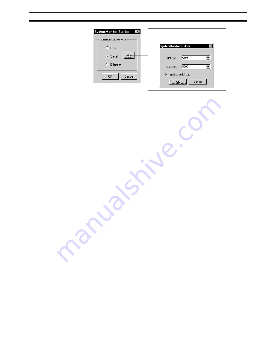
In Network Type, select
CLK
,
Serial
, or
Ethernet
.
If you select
Serial
, set the computer COM port, and the baud rate. If neces-
sary, also set
Initialize serial port
. Refer to the following Note.
Click the
OK
Button to return to the Set Node Dialog Box.
Note
If the communications type is set to Serial (Host Link), then when the monitor
process is started (by clicking the
Run
Button in the Main Window or in the
Setup Dialog Box), FinsGateway Serial Unit driver will start according to the
communications conditions set here.
If you select another communications type (Controller Link or Ethernet), the
communications type set here can be used only from the System Monitor
Screen. You must start the FinsGateway manually.
6.
When you have finished making all the PLC and computer settings, click
the
OK
Button in the System Monitor Settings Window. This completes the
System Monitor settings.
5-4
Creating Graphic Screens
5-4-1
Outline
The Graphic Screen displays schematically the device status.
Create the Graphic Screen using the Graphic Builder.
• Paste to the screen graphic elements representing plant instrumentation,
which have been provided, and use them to display the device status, to a
maximum of 200 screens.
• Library figures and images:
Text, lines, rectangles, round rectangles (rectangles with rounded cor-
ners), ellipses, polygons, and images
• Fixed graphic display elements:
Text boxes, instruments, thermometers, transmitters, and orifices
• Changeable graphic display elements:
Analog inputs: Bar graph displays, numerical value displays, and tanks
Analog settings: Numerical settings (See note.)
Contact inputs (display): Pumps, valves, and pipes
Contact settings (operation): Switches (See note.)
Note
If making analog values or contact settings, use tags for Constant
Generator (Block Model 166) and Internal Switch (Block Model
209).
The Details button will be enabled if you
select
Serial
. If you click the
Details
Button,
the following dialog box will be displayed.
Содержание CX-Process Monitor Plus 2
Страница 1: ...CX Process Monitor Plus Ver 2 Cat No W428 E1 02 SYSMAC WS02 LCMC1 EV2 OPERATION MANUAL...
Страница 2: ...WS02 LCMC1 EV2 CX Process Monitor Plus Ver 2 Operation Manual Revised January 2007...
Страница 3: ...iv...
Страница 5: ...vi...
Страница 9: ...x...
Страница 15: ...xvi Application Precautions 4...
Страница 41: ...26 Basic Operating Procedure Section 1 2...
Страница 243: ...228 Checking Configurations Section 5 7...
Страница 244: ...229 SECTION 6 Troubleshooting This section describes errors that can occur while using the CX Process Monitor Plus...
Страница 267: ...252 Reading Writing Function Block ITEMs Appendix A...
Страница 269: ...254 Differences between Trend Screens and Batch Trend Screens Appendix B...


