OMNI 4000/7000 Operations and Maintenance Guide
– Rev F
7-54
Maintenance
5.
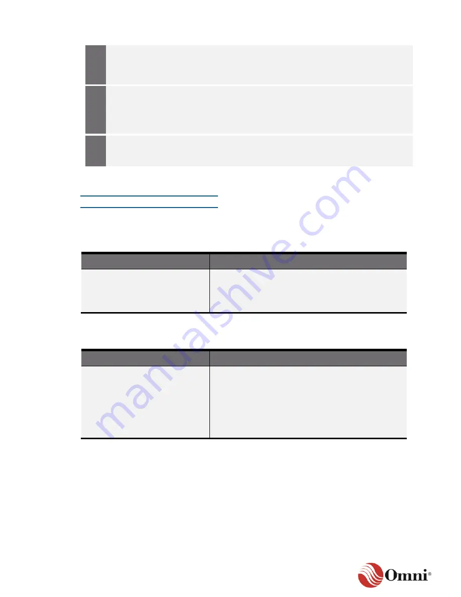
If you want to begin archiving raw data
again, go to Section 5.3.2 and follow the
instructions for starting this feature if it has
stopped.
6.
If you are using PID Loops, start your
batches or open the pipeline system valves
and initiate flow through PID Control (go to
Startup and Shutdown Ramping Functions
in Section 6.6.6).
7.
If you are not using PID Loops to start the
batches, notify your SCADA operator or
technician to initiate flow.
7.4.3 Fuse Service and Replacement
Specifications
Fuses are located on the panel mount and short extended back panels (Table 7-1) or extended
back panels (Table 7-2).
Table 7-1: Power Fuse Specifications
Location
Specifications
•
Standard Back Panel
(4000/7000)
•
Short Extended Back Panel
(7000)
•
AC Fuse 5x20 = 1.6 A Fast Blow
(Littelfuse #021701.6)
•
DC Fuse 5x20 = 3.15 A Slow Blow
(Littelfuse #02183.15)
Table 7-2: NEMA Mount Power Fuse Specifications
Location
Specifications
Extended Back Panel (7000)
•
AC Fuse 5x20 = 1.6 A Fast Blow
(Littelfuse #021701.6)
•
DC Fuse 2AG = 3 A Slow Blow
(Littelfuse #0229003)
•
Transducer Loop power fuses 1 through 8
DC Fuse 2AG = 250 mA Fast Blow
(Littelfuse #0225.250)
Содержание 4000 Series
Страница 1: ...Series 4000 7000 Operations Maintenance Guide...
Страница 21: ...OMNI 4000 7000 Operations and Maintenance Guide Rev F 2 4 OMNI 4000 7000 Overview Figure 2 2 OMNIPANEL...
Страница 23: ...OMNI 4000 7000 Operations and Maintenance Guide Rev F 2 6 OMNI 4000 7000 Overview Figure 2 4 OMNI Modbus Tester...


