


OMNI 4000/7000 Operations and Maintenance Guide
– Rev F
7-5
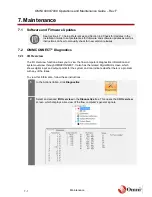
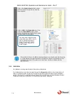
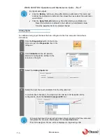
Maintenance
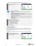
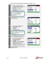
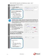
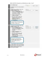
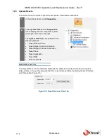
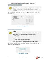
9.
Click
Calibrate Input.
Click
Abort
to abort the current calibration
sequence.
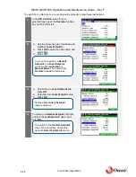
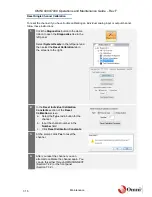
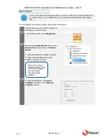
10.
To apply the low calibration value in the
Calibration Values
screen:
a. Adjust the
Signal Generator
or
configure the
Transmitter
, whichever
is connected, to output the lowest
value needed to calibrate.
b. Wait 20 to 30 seconds for the
readings to stabilize.
c. Enter an equivalent value in the
appropriate units into the
Low
Calibration Value
field
(for example, 4 mA or 0.000 °F).
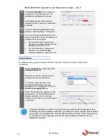
d. Click
Apply Low
.
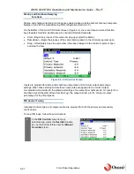
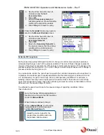
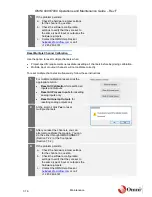
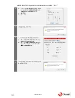
11.
To apply the high calibration value in the
Calibration Values
screen:
a. Adjust the
Signal Generator
or
configure the
Transmitter
to output
the highest value needed for
calibration.
b. Wait 20 to 30 seconds for the
readings to stabilize.
c. Enter an equivalent value in the
appropriate units into the
High
Calibration Value
(for example, 20 mA or 0.000 °F).
d. Click
Apply High
.
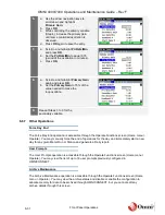
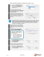
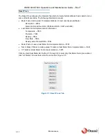
12.
To stop calibration, disconnect any signal
simulators that are being used to calibrate
the input channel, and reconnect the field
instrument wiring according to your
project-specific diagrams.
Low values are 4.00 mA for a 4
‒20
mA input, 1 V for a 1
‒5 V input, and
25 ohms for an RTD input.
High values must be stated for
each type of input: 20.00 mA for a
4
‒20 mA input, 5 V for a 1‒5 V
input, and 150 ohms for an
RTD input.
Содержание 4000 Series
Страница 1: ...Series 4000 7000 Operations Maintenance Guide...
Страница 21: ...OMNI 4000 7000 Operations and Maintenance Guide Rev F 2 4 OMNI 4000 7000 Overview Figure 2 2 OMNIPANEL...
Страница 23: ...OMNI 4000 7000 Operations and Maintenance Guide Rev F 2 6 OMNI 4000 7000 Overview Figure 2 4 OMNI Modbus Tester...


