


OMNI 4000/7000 Operations and Maintenance Guide
– Rev F
7-4
Maintenance
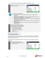
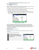
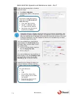
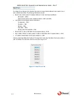
5.
Verify that the signal wiring on the back
panel is correct.
6.
a. Click
Start Calibration
.
b. Click
Yes
to confirm on the pop-up
window.
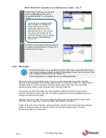
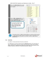
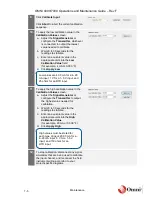
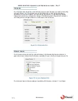
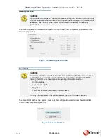
If the Remark field is not filled in during the Analog input channel configuration, then
the Modbus register’s database description, the hardware module and the Terminal
Block pin numbers are still displayed in blue text after a selection is made. If the input
channel is unassigned, only the hardware module and Terminal Block pin numbers
are still displayed in blue text.
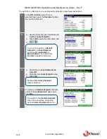
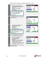
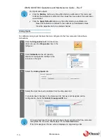
7.
If you are calibrating an input that has
been assigned, the
Set Override
group
will appear and you will be able to enter
the override value:
a. Verify or edit the default value and
then click
Apply Override
.
b. Go to to Step 10.
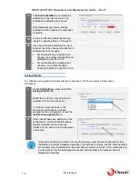
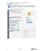
If you are calibrating an input that has not
been assigned, only the
Calibration Units
group will appear (it will skip the
Set
Override
group). Continue to Step 8.
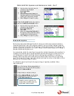
8.
Select the type of signal (for which the
channel has been configured with the
hardware jumpers) and click
Apply Units
.
This action records the following
information in the
Measurement
Audit Trail Log
:
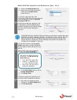
•
Time, date and I/O index
•
Input # ‘n’ calibration start
(n = input channel number)
•
User name, user ID and port
used for the calibration
The unit options are:
•
mA
•
Volts
•
Ohms (if the channel has
been configured for an RTD
type signal)
•
Engineering units (if an I/O
channel is assigned)
)
Содержание 4000 Series
Страница 1: ...Series 4000 7000 Operations Maintenance Guide...
Страница 21: ...OMNI 4000 7000 Operations and Maintenance Guide Rev F 2 4 OMNI 4000 7000 Overview Figure 2 2 OMNIPANEL...
Страница 23: ...OMNI 4000 7000 Operations and Maintenance Guide Rev F 2 6 OMNI 4000 7000 Overview Figure 2 4 OMNI Modbus Tester...


